Subaru Legacy IV (2008 year). Service manual - part 1172


  Index      Subaru     Subaru Legacy IV - service and repair manual 2008 year


Search            


Content   ..  1170  1171  1172  1173   ..


Subaru Legacy IV (2008 year). Service manual - part 1172
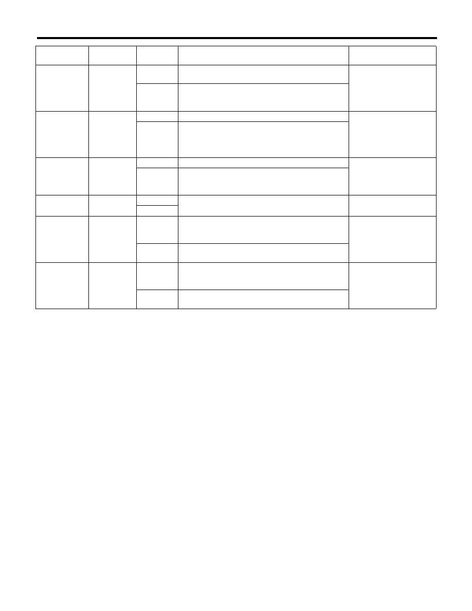


LAN(diag)-22

Subaru Select Monitor

LAN SYSTEM (DIAGNOSTICS)

5) After setting, make sure that vehicle equipment is same as the setting changed in the {Current Data Dis-
play & Save}.

CAUTION:
• The above settings must match the actual vehicle equipment for proper operation.
• Do not change settings except for setting above while setting the functions.
• Be sure not to change Factory or Market setting except when installing a new body integrated unit.

NOTE:
For details concerning the operation procedure, refer to the “PC application help for Subaru Select Monitor”.

Ans.-back 
Buzzer

ON

ON

Vehicle is controlled in answer-back buzzer equipped 
mode.

OFF

Vehicle is controlled in answer-back buzzer non-
equipped mode. (Always set to OFF for vehicles not 
equipped with the answer-back.)

Initial keyless 
setting

 — 

 — 

 — 

Execution

Settings of keyless entry system are initialized. (Auto-
lock time: 30 sec., Answer-back buzzer setup: ON, 
Hazard answer-back setup: ON, Automatic locking 
setup: ON, Ans.-back Buzzer: ON)

Initial button 
setting

 — 

 — 

 — 

Execution

Settings of each function are initialized. (Off delay 
time: Normal, R defogger op. mode: 15 min., Wiper 
deicer op. mode: 15 min., Lockout prevention: ON)

Passive Alarm

OFF

ON

Workable when passive arming is set to “ON.”


OFF

Door open 
warning (pre-
vention of bat-
tery run-out)

ON

ON

If detecting door open for 10 minutes, room light, key 
illumination and door warning light are turned off to 
prevent battery run-out.

OFF

Room light, key illumination and door warning light is 
not turned off.

Belt Warning 
Switch

OFF

ON

Alarm is set off with the indicator lit and buzzer beep 
from the first to third stage according to the vehicle 
speed and whether or not seat belts are worn.

OFF

Turns off the indicator and stops buzzer except for the 
first stage.

Data

Initial setting 

value

Customize 

setting

Remarks

Destination Specifications

LAN(diag)-23

Subaru Select Monitor

LAN SYSTEM (DIAGNOSTICS)

10.FUNCTION CHECK

In order to check the body integrated unit function,
inspect the body integrated unit and actuator using
Subaru Select Monitor without operating switches.
1) On the «Main Menu» display, select the {Each
System Check}.
2) On the «System Selection Menu» display, select
the {Integ. unit mode}.
3) On the «Integ. unit mode failure diag» display,
select the {Function check}.
4) Select the item to be operated on the «Function
check» display screen with «UP/Down key» and
select the [OK].

5) Pressing [OK] starts, [NO] cancels the operation
and [OK] returns to the System Operation Check
Mode display screen.

NOTE:
If not equipped (based on area or condition), pro-
cess will not go on.

LAN00018

HEATER  COCK VALVE OUTPUT
DOOR LOCK ACTUATOR LOCK OUTPUT
ALL SEAT UNLOCK OUTPUT
HORN OUTPUT
R GATE/TRUNK UNLK OUTPUT
DOUBLE LOCK OUTPUT
SHIFT LOCK SOLENOID
KEY LOCK OUTPUT

FUNCTION CHECK

LAN(diag)-24

Subaru Select Monitor

LAN SYSTEM (DIAGNOSTICS)

B: INSPECTION

1. COMMUNICATION FOR INITIALIZING IMPOSSIBLE

DETECTING CONDITION:
Faulty harness connectors
TROUBLE SYMPTOM:
Not communicable with Subaru Select Monitor.
WIRING DIAGRAM:

7

A1

B19

1 2 3 4 5 6 7 8

9 10 11 12 13 14 15 16

B40

i84

A:

B280

B:

B40

i84

A:

B280

B:

5 6 7

8

2

1

9

4

3

10

24

22 23

25

11 12 13 14 15

26

27 28

16 17 18 19

20 21

1 2

3 4

5 6

7 8

9 10 11 12 13 14 15 16 17 18 19 20 21 22 23

24 25

26 27 28 29

30 31 32 33

34 35

LAN00272

BODY INTEGRATED 

UNIT

DATA LINK CONNECTOR

IGNITION
KEY SWITCH

LAN(diag)-25

Subaru Select Monitor

LAN SYSTEM (DIAGNOSTICS)

Step

Check

Yes

No

1

CHECK IGNITION SWITCH.

Is the ignition switch ON?

Go to step 2.

Turn the ignition 
switch to ON, and 
select Integ. Unit 
mode using Sub-
aru Select Monitor.

2

CHECK BATTERY.
1) Turn the ignition switch to OFF.
2) Measure the battery voltage.

Is the voltage 11 V or more?

Go to step 3.

Charge or replace 
the battery.

3

CHECK BATTERY TERMINAL.

Is there poor contact at the bat-
tery terminal?

Repair or tighten 
the battery termi-
nal.

Go to step 4.

4

CHECK COMMUNICATION OF SUBARU SE-
LECT MONITOR.
1) Turn the ignition switch to ON.
2) Using the Subaru Select Monitor, check 
whether communication to other system can be 
executed normally.

Is the system name displayed? Go to step 7.

Go to step 5.

5

CHECK COMMUNICATION OF SUBARU SE-
LECT MONITOR.
1) Turn the ignition switch to OFF.
2) Disconnect the body integrated unit connec-
tor.
3) Turn the ignition switch to ON.
4) Check whether communication to other sys-
tems can be executed normally.

Is the system name displayed? Go to step 7.

Go to step 6.

6

CHECK HARNESS CONNECTOR BETWEEN 
EACH CONTROL UNIT AND SUBARU SE-
LECT MONITOR.
1) Turn the ignition switch to ON.
2) Disconnect the body integrated unit connec-
tor.
3) Measure the resistance between data link 
connector and chassis ground.

Connector & terminal

(B40) No. 7 — Chassis ground:

Is the resistance 1 M

: or 

more?

Go to step 7.

Repair the harness 
and connector 
between each con-
trol unit and Sub-
aru Select Monitor.

7

CHECK OUTPUT SIGNAL TO BODY INTE-
GRATED UNIT.
1) Turn the ignition switch to ON.
2) Measure the voltage between body inte-
grated unit and chassis ground.

Connector & terminal

(B40) No. 7 (+) — Chassis ground (–):

Is the voltage less than 1 V?

Go to step 8.

Repair the harness 
and connector 
between each con-
trol unit and Sub-
aru Select Monitor.

8

CHECK HARNESS CONNECTOR BETWEEN 
BODY INTEGRATED UNIT AND DATA LINK 
CONNECTOR.
Measure the resistance between body inte-
grated unit and data link connector.

Connector & terminal

(B40) No. 7 — (B280) No. 19:

Is the resistance less than 1 

:? Go to step 9.

Repair the harness 
and connector 
between body inte-
grated unit and 
Subaru Select 
Monitor.

9

CHECK INSTALLATION OF BODY INTE-
GRATED UNIT CONNECTOR.
Turn the ignition switch to OFF.

Is the body integrated unit con-
nector inserted into body inte-
grated unit until the clamp locks 
onto it?

Go to step 10.

Insert the body 
integrated unit con-
nector into body 
integrated unit.

10

CHECK POWER SUPPLY CIRCUIT.
1) Turn the ignition switch to ON (engine OFF).
2) Measure the ignition voltage between body 
integrated unit connector and chassis ground.

Connector & terminal

(i84) No. 1 (+) — Chassis ground (–):

Is the voltage 10 V or more?

Go to step 11.

Repair the open 
circuit of harness 
between body inte-
grated unit and 
battery.


Content   ..  1170  1171  1172  1173   ..