Subaru Legacy IV (2008 year). Service manual - part 117
 

  Index      Subaru     Subaru Legacy IV - service and repair manual 2008 year


Search            


Content   ..  115  116  117  118   ..


Subaru Legacy IV (2008 year). Service manual - part 117


EN(H4SO)(diag)-71

Diagnostics for Engine Starting Failure

ENGINE (DIAGNOSTICS)

D: IGNITION CONTROL SYSTEM

CAUTION:
After repair or replacement of faulty parts, perform Clear Memory Mode <Ref. to EN(H4SO)(diag)-50,
Clear Memory Mode.>, and Inspection Mode <Ref. to EN(H4SO)(diag)-41, Inspection Mode.>.
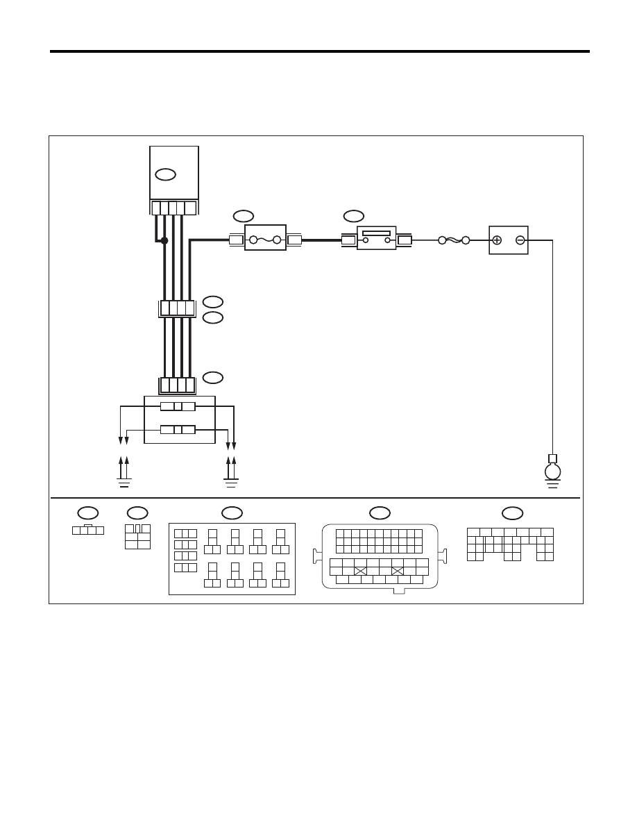
WIRING DIAGRAM:

EN-05701

B137

5

6

7

8

2

1

9

4

3

10

22 23

11 12 13 14 15

24 25

26

16 17

18 19 20 21

27

28 29

30 31

5

3

19

B21

E2

E12

SBF-7

15A

32

49

33

47

1

2

3

4

B137

18

26

6

3

4

1

2

B47

E

1

2

B225

B21

1 2 3 4

12 13 14 15

5 6 7 8

16 17 18 19

9 10 11

20 21 22

23 24 25 26 27 28 29 30 31 32 33

35

34

37

36

39

38

41

40

43

42

44

45

47

46

49

48

51

50

53

52

54

3

4

1

2

5

6

B47

1 2 3 4

E12

9

10

1

2

3

4

5

6

7

8

11 12

14

15 16

13

18

19 20

17

22

23 24

21

38

39 40

37

34

35 36

33

30

31 32

29

26

27 28

25

B225

ECM

RELAY BLOCK

MAIN RELAY

BATTERY

IGNITION COIL 

&

IGNITOR ASSY

EN(H4SO)(diag)-72

Diagnostics for Engine Starting Failure

ENGINE (DIAGNOSTICS)

Step

Check

Yes

No

1

CHECK IGNITION SYSTEM FOR SPARKS.
1) Remove the plug cord cap from each spark 
plug.
2) Install a new spark plug on plug cord cap.

CAUTION:
Do not remove the spark plug from engine.
3) Contact the spark plug’s thread portion to 
the engine.
4) While opening the throttle valve fully, crank 
the engine to check that spark occurs at each 
cylinder.

Does spark occur at each cylin-
der?

Check fuel pump 
system. <Ref. to 
EN(H4SO)(diag)-
74, FUEL PUMP 
CIRCUIT, Diag-
nostics for Engine 
Starting Failure.>

Go to step 2.

2

CHECK POWER SUPPLY CIRCUIT FOR IG-
NITION COIL AND IGNITOR ASSEMBLY.
1) Turn the ignition switch to OFF.
2) Disconnect the connector from the ignition 
coil & ignitor assembly.
3) Turn the ignition switch to ON.
4) Measure the voltage between ignition coil 
and ignitor assembly connector and engine 
ground.

Connector & terminal

(E12) No. 2 (+) — Engine ground (–):

Is the voltage 10 V or more?

Go to step 3.

Repair the harness 
and connector.

NOTE:
In this case, repair
the following item:
• Open circuit of
harness between
the ignition coil and
ignitor assembly,
and main relay
connector
• Poor contact of
coupling connector
• Blown out of fuse

3

CHECK HARNESS BETWEEN ECM AND IG-
NITION COIL AND IGNITOR ASSEMBLY.
1) Turn the ignition switch to OFF.
2) Measure the resistance between the igni-
tion coil and ignitor assembly connector and the 
ECM.

Connector & terminal

(E12) No. 3 — (B137) No. 6:
(E12) No. 3 — (B137) No. 26:

Is the resistance less than 1 

:? Go to step 4.

Repair the harness 
and connector.

NOTE:
In this case, repair
the following item:
• Open circuit in
harness between
ECM and ignition
coil and ignitor as-
sembly connector
• Poor contact of
coupling connector

4

CHECK IGNITION COIL AND IGNITOR AS-
SEMBLY.
1) Remove the spark plug cords.
2) Measure the resistance between spark plug 
cord contact portions to check secondary coil.

Terminals

No. 1 — No. 2:
No. 3 — No. 4:

Is the resistance between 10 and 
15 k

:?

Go to step 5.

Replace the igni-
tion coil and ignitor 
assembly. <Ref. to 
IG(H4SO)-6, Igni-
tion Coil and Ignitor 
Assembly.>

5

CHECK INPUT SIGNAL FOR IGNITION COIL 
AND IGNITOR ASSEMBLY.
1) Connect the connector to the Ignition coil 
and ignitor assembly.
2) Check if voltage varies synchronously with 
engine speed when cranking, while monitoring 
voltage between ignition coil and ignitor assem-
bly connector and engine ground.

Connector & terminal

(E12) No. 1 (+) — Engine ground (–):
(E12) No. 4 (+) — Engine ground (–):

Does the voltage vary 10 V or 
more?

Go to step 6.

Replace the igni-
tion coil and ignitor 
assembly. <Ref. to 
IG(H4SO)-6, Igni-
tion Coil and Ignitor 
Assembly.>

EN(H4SO)(diag)-73

Diagnostics for Engine Starting Failure

ENGINE (DIAGNOSTICS)

6

CHECK HARNESS BETWEEN ECM AND IG-
NITION COIL AND IGNITOR ASSEMBLY 
CONNECTOR.
1) Turn the ignition switch to OFF.
2) Disconnect the connectors from ECM.
3) Disconnect the connector from the ignition 
coil & ignitor assembly.
4) Measure the resistance of harness between 
ECM and ignition coil and ignitor assembly con-
nector.

Connector & terminal

(B137) No. 18 — (E12) No. 1:
(B137) No. 19 — (E12) No. 4:

Is the resistance less than 1 

:? Go to step 7.

Repair the harness 
and connector.

NOTE:
In this case, repair
the following item:
• Open circuit in
harness between
ECM and ignition
coil and ignitor as-
sembly connector
• Poor contact of
coupling connector

7

CHECK HARNESS BETWEEN ECM AND IG-
NITION COIL AND IGNITOR ASSEMBLY 
CONNECTOR.
Measure the resistance of harness between 
ECM and engine ground.

Connector & terminal:

(B137) No. 18 — Engine ground:
(B137) No. 19 — Engine ground:

Is the resistance 1 M

: or 

more?

Repair the poor 
contact of ECM 
connector.

Repair the ground 
short circuit of har-
ness between 
ECM and ignition 
coil and ignitor 
assembly connec-
tor.

Step

Check

Yes

No

EN(H4SO)(diag)-74

Diagnostics for Engine Starting Failure

ENGINE (DIAGNOSTICS)

E: FUEL PUMP CIRCUIT

CAUTION:
After repair or replacement of faulty parts, perform Clear Memory Mode <Ref. to EN(H4SO)(diag)-50,
OPERATION, Clear Memory Mode.>, and Inspection Mode <Ref. to EN(H4SO)(diag)-41, PROCEDURE,
Inspection Mode.>.
WIRING DIAGRAM:

Step

Check

Yes

No

1

CHECK OPERATING SOUND OF FUEL 
PUMP.
Make sure that the fuel pump operates for two 
seconds when turning the ignition switch to ON.

NOTE:
Fuel pump operation can be executed using the
Subaru Select Monitor.
For the procedures, refer to “Compulsory Valve
Operation Check Mode”. <Ref. to
EN(H4SO)(diag)-51, Compulsory Valve Opera-
tion Check Mode.>

Does the fuel pump emit oper-
ating sound?

Check the fuel 
injector circuit. 
<Ref. to 
EN(H4SO)(diag)-
76, FUEL INJEC-
TOR CIRCUIT, 
Diagnostics for 
Engine Starting 
Failure.>

Go to step 2.

EN-06832

5

3

B97

MAIN SBF

No. 12

SBF-6

E

3

1

B72

B362

B136

No. 11

FUEL PUMP
RELAY

FUEL PUMP

FUEL PUMP

CONDENSER

ECM

BATTERY

IGNITION
SWITCH

B136

B72

1

3

4 5 6

2

R142

R58

5
6

7 8

3
4

1 2

B362

1
2

1
2

R58

M

6

5

E

R142

2

1

B97

R1

20

R67

R46

12

R67

1

2

3 4 5 6

1 2 3 4

5 6 7 8 9

10 11 12 13 14 15 16 17 18 19 20

1
4
3
2

16

10 11 12 13 14 15

25

24

30

9

8

7

17 18 19 20
28

21 22 23

29

32

31

1

2

3

4

5

6

27

26

33 34 35

 : SEDAN MODEL

 :

SD

SD

SD

1 2
3 4
5 6


Content   ..  115  116  117  118   ..