Subaru Legacy IV (2008 year). Service manual - part 67
ME(H4SO)-64
Cylinder Head
MECHANICAL
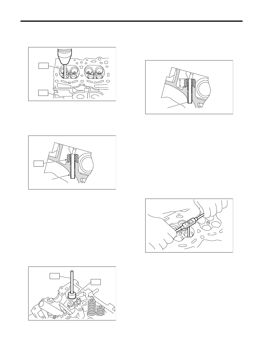
(2) Insert the ST2 into valve guide and press it
down to remove the valve guide.
ST1
498267800
CYLINDER HEAD TABLE
ST2
499767200
VALVE GUIDE REMOVER
(3) Turn the cylinder head upside down and
place the ST as shown in the figure.
Intake side
ST
499767700
VALVE GUIDE ADJUSTER
Exhaust side
ST
499767800
VALVE GUIDE ADJUSTER
(4) Before installing a new valve guide, make sure
that neither scratches nor damages exist on the in-
ner surface of valve guide holes in cylinder head.
(5) Put a new valve guide, coated with sufficient
oil, in cylinder, and insert the ST1 into valve
guide. Press in until the valve guide upper end
is flush with the upper surface of ST2.
ST1
499767200
VALVE GUIDE REMOVER
Intake side
ST2
499767700
VALVE GUIDE ADJUSTER
Exhaust side
ST2
499767800
VALVE GUIDE ADJUSTER
(6) Check the valve guide protrusion.
Valve guide protrusion L:
Intake
20.0 — 21.0 mm (0.787 — 0.827 in)
Exhaust
16.5 — 17.5 mm (0.650 — 0.689 in)
(7) Ream the inside of valve guide using ST.
Put the ST in valve guide, and rotate the ST
slowly clockwise while pushing it lightly. Bring
the ST back while rotating it clockwise.
NOTE:
• Apply engine oil to the ST when reaming.
• If the inner surface of valve guide is damaged,
the edge of ST should be slightly ground with oil
stone.
• If the inner surface of valve guide becomes lus-
trous and the ST does not chip, use a new ST or
remedy the ST.
ST
499767400
VALVE GUIDE REAMER
(8) After reaming, clean the valve guide to re-
move chips.
(9) Recheck the contact condition between
valve and valve seat after replacing the valve
guide.
(A) Valve guide
ME-00290
ST2
ST1
(A)
ME-00291
ST
ST2
ME-00292
ST1
(A) Valve guide
ME-00293
(A)
L
ME-00294