Content .. 1011 1012 1013 1014 ..
Subaru Legacy III (2000-2003 year). Service manual - part 1013
WI-6
WIRING SYSTEM
BASIC DIAGNOSTICS PROCEDURE
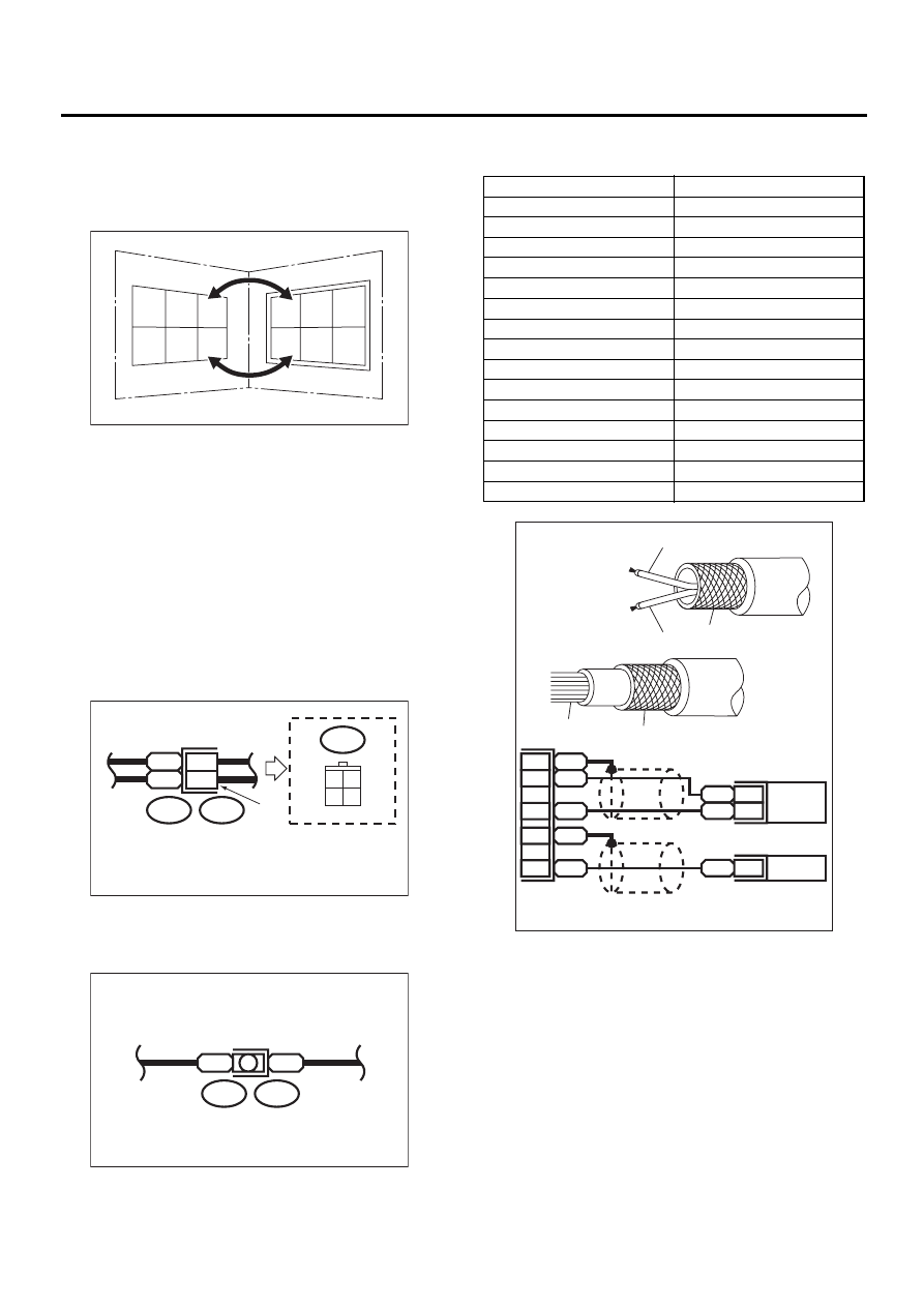
• When one set of connectors is viewed from the
front side, the pole numbers of one connector are
symmetrical to those of the other. When these two
connectors are connected as a unit, the poles
which have the same number are joined.
• Electrical wiring harness:
The connectors are numbered along with the num-
ber of poles, external colors, and mating connec-
tions in the accompanying list.
• The sketch of each connector in the wiring dia-
gram usually shows the (A) side of the connector.
The relationship between the wire color, terminal
number and connector is described in figure.
NOTE:
A wire which runs in one direction from a connector
terminal sometimes may have a different color from
that which runs in the other direction from that ter-
minal.
• In wiring diagram, connectors which have no ter-
minal number refer to one-pole types. Sketches of
these connectors are omitted intentionally.
• The following color codes are used to indicate
the colors of the wires used.
WI-00107
1
1
2
2
3
3
4
4
5
5
6
6
WI-00108
Wire color :
BR (No. 1 terminal)
RW (No. 3 terminal)
i2
3 4
1 2
BR
RW
i2
F4
1
3
(A)
WI-00109
B
B
B15
F10
Color code
Color
L
Blue
B
Black
Y
Yellow
G
Green
R
Red
W
White
Br
Brown
Lg
Light green
Gr
Gray
P
Pink
Or
Orange
Lb
Light Blue
V
Violet
SA
Sealed (Inner)
SB
Sealed (Outer)
WI-00110
YL
2
YG
1
SB
10
YL
9
YG
8
SA
1
SB
22
SA
20
YG
YL
SB
SB
SA