Subaru Legacy (2005 year). Service manual - part 544
 

  Index      Subaru     Subaru Legacy - service and repair manual 2005 year


Search            


Content   ..  542  543  544  545   ..


Subaru Legacy (2005 year). Service manual - part 544


4AT(diag)-13

AUTOMATIC TRANSMISSION (DIAGNOSTICS)

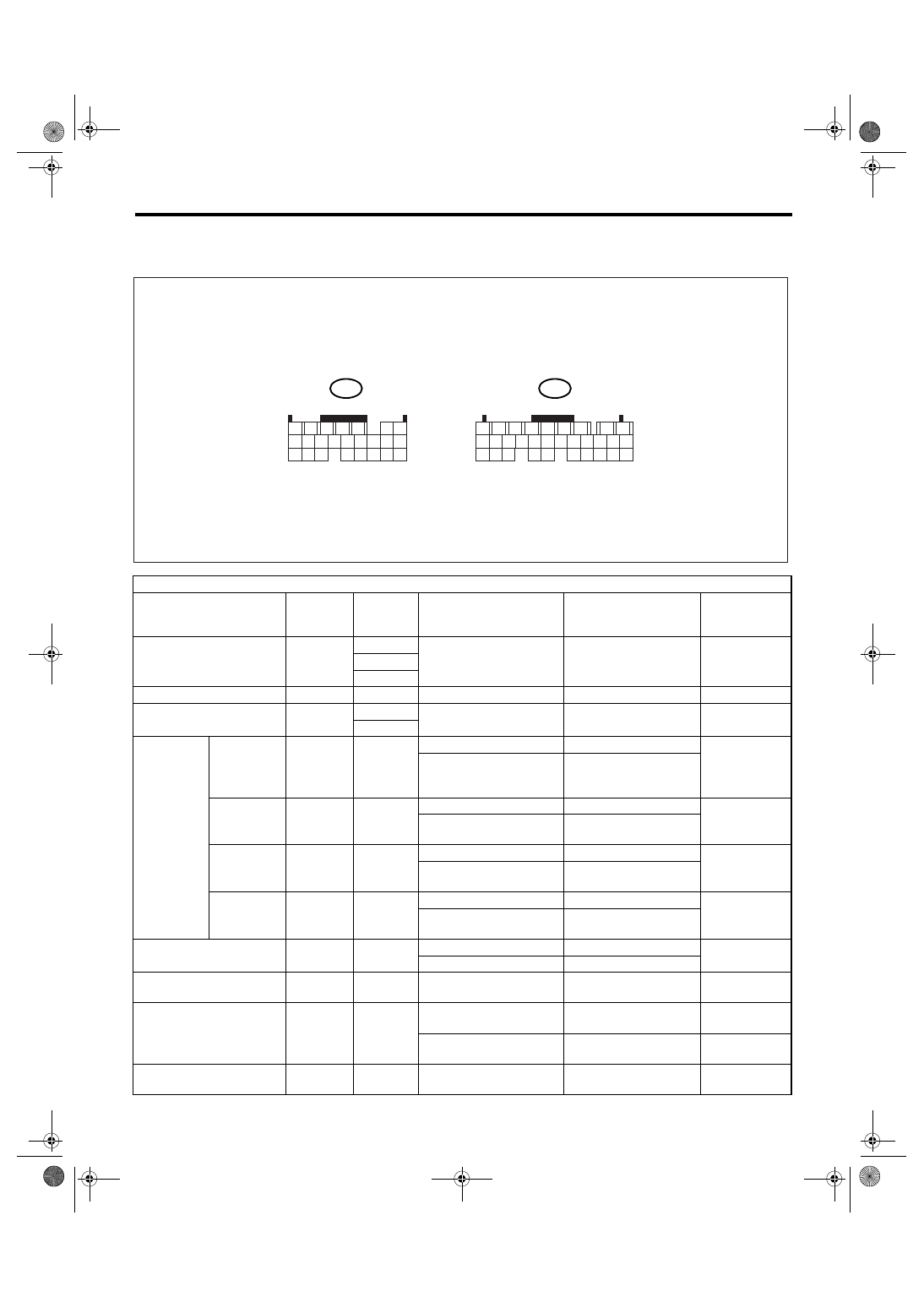
Transmission Control Module (TCM) I/O Signal

5. Transmission Control Module (TCM) I/O Signal

A: ELECTRICAL SPECIFICATION

Check with ignition switch ON.

Item

Connector 

No.

Terminal 

No.

Measuring conditions

Voltage (V)

Resistance to 

chassis ground 

(

Ω)

Back-up power supply

B55

27

Ignition switch OFF

10 — 13

28

29

ACC power supply

B55

16

Ignition switch ACC

10 — 13

Ignition power supply

B55

21

Ignition switch ON (with 

engine OFF)

10 — 13

31

Inhibitor 
switch

“P” range 
switch

B54

5

Selector lever in “P” range

Less than 1

Select lever in any other 

than “P” range (except “N” 

range)

8 or more

“N” range 
switch

B54

22

Selector lever in “N” range

Less than 1

Selector lever in any other 

than “N” range

8 or more

“R” range 
switch

B54

14

Selector lever in “R” range

Less than 1

Selector lever in any other 

than “R” range

8 or more

“D” range 
switch

B54

4

Selector lever in “D” range

Less than 1

Selector lever in any other 

than “D” range

8 or more

Accelerator pedal position 
sensor

B54

19

Throttle fully closed.

0.2 or more

Throttle fully open.

4.6 or less

Accelerator pedal position 
sensor power supply

B54

10

Ignition switch ON (with 

engine OFF)

Approx. 4.6 — 5.4

ATF temperature sensor

B54

21

ATF temperature 20

°C 

(68

°F)

3.5 — 4.3

2.3 k — 5.3 k

ATF temperature 80

°C 

(176

°F)

1.0 — 2.2

300 — 800

Rear vehicle speed sensor

B54

24

Vehicle speed at least 20 

km/h (12 MPH)

2 or more (AC range)

AT-01476

B54

B55

1

2

7

8

9

5

6

3

4

10

11

12

19

20

21

13

14

15

16

17

18

22

23

24

1

2

7

8

9

5

6

3

4

10

11

12

19

20

21

29

30

31

13

14

15

16

17

27

28

18

22

23

24

25

26

To

To

4AT(diag)-14

AUTOMATIC TRANSMISSION (DIAGNOSTICS)

Transmission Control Module (TCM) I/O Signal

Front vehicle speed sensor

B54

6

Vehicle stopped

0

450 — 750

Vehicle speed at least 20 

km/h (12 MPH)

1 or more (AC range)

Torque converter turbine 
speed sensor

B54

7

Engine idling after warm-

up (“D” range)

0

450 — 750

Engine idling after warm-

up (“N” range)

1 or more (AC range)

Engine speed signal

B54

13

Ignition switch ON (with 

engine OFF)

Less than 1

Ignition switch ON (engine 

ON)

5 or more (AC range)

Line pressure linear sole-
noid

B55

20

Ignition switch ON (with 

engine OFF)

Throttle fully closed in “R” 

range after warm-up.

3.7 — 7.5

4.0 — 8.0

Ignition switch ON (with 

engine OFF)

“R” range throttle fully 

open after warm-up.

1.4 — 4.9

Lock-up duty solenoid

B55

5

When lock up occurs.

10.5 or more

2.0 — 6.0

When lock up is released.

Less than 1

Transfer duty solenoid

B55

4

“P” or “N” range

Less than 1

2.0 — 6.0

1st gear

1.7 — 4.0

2-4 brake duty solenoid

B55

6

“P” or “N” range

10.5 or more

2.0 — 6.0

2nd or 4th gear

Less than 1

High clutch duty solenoid

B55

8

3rd or 4th gear

Less than 1

2.0 — 6.0

“P” or “N” range

10.5 or more

Low clutch duty solenoid

B55

9

1st or 2nd gear

Less than 1

2.0 — 6.0

“P” or “N” range

10.5 or more

Low & reverse duty solenoid

B55

7

“P” or “N” range

10.5 or more

2.0 — 6.0

Driving at 1st on manual 

mode (15 km/h (9.3 MPH) 

or more)

5 — 10

Front vehicle speed sensor 
ground

B54

15

0

Less than 1

Rear vehicle speed sensor 
ground

B54

23

0

Less than 1

Torque converter turbine 
speed sensor ground

B54

16

0

Less than 1

System ground circuit

B54

17

0

Less than 1

B55

2

B55

3

B54

8

Sensor ground line 3

B55

19

0

Less than 1

Sensor ground line 4

B54

9

0

Less than 1

Range lock signal

B55

18

“D” range vehicle speed

0 km/h (0 MPH)

10.5 or more

7 — 18

“D” range vehicle speed

20 km/h (12 MPH)

Less than 1

Data link signal (Subaru 
Select Monitor)

B55

12

Check with ignition switch ON.

Item

Connector 

No.

Terminal 

No.

Measuring conditions

Voltage (V)

Resistance to 

chassis ground 

(

Ω)

4AT(diag)-15

AUTOMATIC TRANSMISSION (DIAGNOSTICS)

Transmission Control Module (TCM) I/O Signal

CAN communication signal 
(+)

B54

3

Ignition switch ON

Pulse signal

CAN communication signal 
(

−)

B54

12

Ignition switch ON

Pulse signal

FWD switch

B55

17

Fuse removed

10.5 or more

Fuse installed

1 or less

Lateral G sensor

B54

11

Ignition switch ON (Lateral 

G sensor in horizontal 

position)

2.0 — 3.0

Lateral G sensor power sup-
ply

B54

2

Ignition switch ON

4.75 — 5.25

Check with ignition switch ON.

Item

Connector 

No.

Terminal 

No.

Measuring conditions

Voltage (V)

Resistance to 

chassis ground 

(

Ω)

4AT(diag)-16

AUTOMATIC TRANSMISSION (DIAGNOSTICS)

Subaru Select Monitor

6. Subaru Select Monitor

A: OPERATION

1. READ DIAGNOSTIC TROUBLE CODE 
(DTC)

1) Prepare the Subaru Select Monitor kit.

2) Connect the diagnosis cable to Subaru Select
Monitor.
3) Insert the cartridge to Subaru Select Monitor.
<Ref. to 4AT(diag)-6, PREPARATION TOOL, Gen-
eral Description.>

4) Connect the Subaru Select Monitor to data link
connector.

(1) Data link connector is located in the lower
portion of instrument panel (on the driver’s side).

(2) Connect the diagnosis cable to data link
connector.

NOTE:
Do not connect scan tools except Subaru Select
Monitor.
5) Turn the ignition switch to ON (engine OFF), and
turn the Subaru Select Monitor power switch to ON.

6) On the «Main Menu» display screen, select the
{Each System Check} and press the [YES] key.
7) On the «System Selection Menu» display
screen, select the {Transmission} and press the
[YES] key.
8) Press the [YES] key after the information of
transmission type is displayed.
9) On the «Transmission Diagnosis» display
screen, select the {Diagnosis Code(s) Display} and
press [YES] key.

NOTE:
• For details concerning operation procedure, re-
fer to the SUBARU SELECT MONITOR OPERA-
TION MANUAL.
• For details concerning DTC, refer to “List of Diag-
nostic Trouble Code (DTC)”. <Ref. to 4AT(diag)-
31, List of Diagnostic Trouble Code (DTC).>

2. READ CURRENT DATA

1) On the «Main Menu» display screen, select the
{Each System Check} and press the [YES] key.
2) On the «System Selection Menu» display
screen, select the {Transmission} and press the
[YES] key.
3) Press the [YES] key after the information of
transmission type is displayed.
4) On the «Transmission Diagnosis» display
screen, select the {Current Data Display & Save}
and press the [YES] key.
5) On the «Transmission Diagnosis» display
screen, select the {Data Display} and press the
[YES] key.
6) Using the scroll key, scroll the display screen up
or down until the desired data is shown.

(1) Data link connector

AT-00338

AT-00339

AT-01712

(1)

(A) Power switch

(A)

AT-00341


Content   ..  542  543  544  545   ..