Subaru Legacy (2005 year). Service manual - part 147
 

  Index      Subaru     Subaru Legacy - service and repair manual 2005 year


Search            


Content   ..  145  146  147  148   ..


Subaru Legacy (2005 year). Service manual - part 147


EN(H4SO 2.0)(diag)-177

ENGINE (DIAGNOSTICS)

Diagnostic Procedure with Diagnostic Trouble Code (DTC)

BC:DTC P1137 O2 SENSOR CIRCUIT (BANK1 SENSOR1)

DTC DETECTING CONDITION:
Immediately at fault recognition

CAUTION:
After repair or replacement of faulty parts, perform Clear Memory Mode <Ref. to EN(H4SO 2.0)(diag)-
38, OPERATION, Clear Memory Mode.> 
and Inspection Mode <Ref. to EN(H4SO 2.0)(diag)-32, PRO-
CEDURE, Inspection Mode.>.
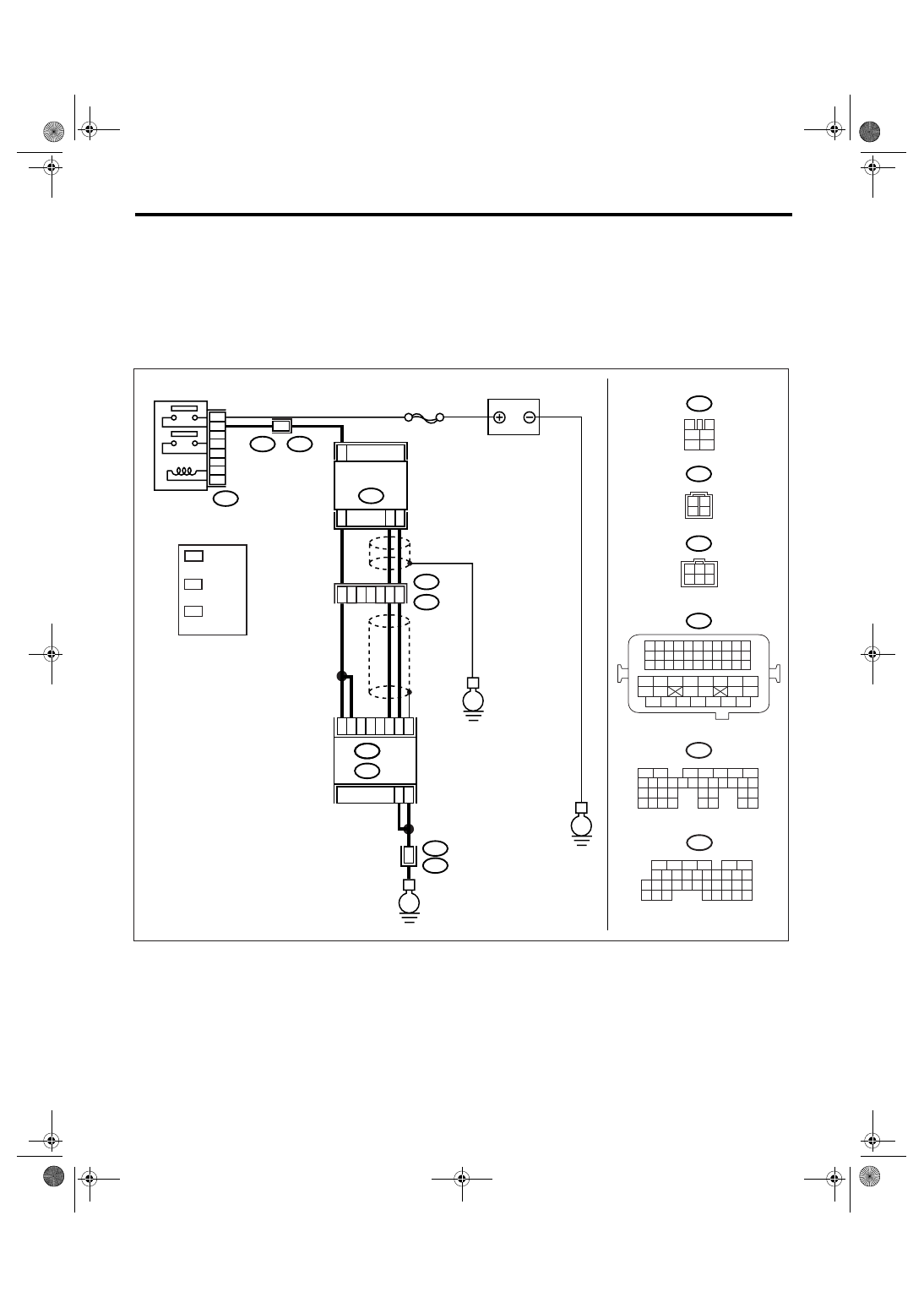
WIRING DIAGRAM:

EN-03475

3

4

1

2

5

6

B47

SBF-5

E

B47

E24

5
3

4
6

2
1

C34

C35

C33

B3

B2

B1

B135

E

B5

B6

52

B21

E2

B21

E2

50

51

3

4

E2

B21

E

B21

1 2 3 4

12 13 14 15

5 6 7 8

16 17 18 19

9 10 11

20 21 22

23 24 25 26 27 28 29 30 31 32 33

35

34

37

36

39

38

41

40

43

42

44

45

47

46

49

48

51

50

53

52

54

E24

ECM

BATTERY

FRONT OXYGEN

(A/F) SENSOR

MAIN RELAY

B136

B:

C:

1

2

3

4

B135

5

6

7

8

2

1

9

4

3

10

24

22 23

25

11 12 13 14 15

26 27

28

16 17 18 19

20 21

29 30 31

32 33

34 35

B:

B136

5

6

7 8

2

1

9

4

3

10

24

22 23

25

11 12 13 14 15

26 27

28

16

17 18 19 20 21

33 34

29

32

30

31

35

C:

E24

3

2

*

1

*

*

3

  LHD : 4

RHD : 1

*

1

*

*

2

3

3

1

6 5 4

2

: RHD

: LHD

LHD : 1

RHD : 4

LHD : 2

RHD : 6

EN(H4SO 2.0)(diag)-178

ENGINE (DIAGNOSTICS)

Diagnostic Procedure with Diagnostic Trouble Code (DTC)

Step

Check

Yes

No

1

CHECK ANY OTHER DTC ON DISPLAY.

Is any other DTC displayed?

Check DTC using 
“List of Diagnostic 
Trouble Code 
(DTC)”. <Ref. to 
EN(H4SO 
2.0)(diag)-64, List 
of Diagnostic Trou-
ble Code (DTC).>

Go to step 2.

2

CHECK FRONT OXYGEN (A/F) SENSOR DA-
TA.
1) Start the engine.
2) While observing the Subaru Select Monitor 
or general scan tool screen, warm-up the 
engine until engine coolant temperature is 
above 70

°C (160°F).

If the engine is already warmed-up, operate at 
idle speed for at least 1 minute.
3) Read the data of front oxygen (A/F) sensor 
signal during idling using Subaru Select Moni-
tor or general scan tool.

NOTE:

• Subaru Select Monitor
For detailed operation procedure, refer to 
“READ CURRENT DATA FOR ENGINE”. <Ref. 
to EN(H4SO 2.0)(diag)-25, Subaru Select 
Monitor.>
• General scan tool
For detailed operation procedure, refer to the 
general scan tool operation manual.

Is the voltage 0.85 — 1.15 V?

Go to step 3.

Go to step 4.

3

CHECK FRONT OXYGEN (A/F) SENSOR DA-
TA.
Race the engine at speeds from idling to 5,000 
rpm for a total of 5 cycles.

NOTE:

• Air fuel ratio is rich at normal condition or 
during racing.
• To increase engine speed to 5,000 rpm, 
slowly depress accelerator pedal, taking 
approximately 5 seconds, and quickly release 
accelerator pedal to decrease engine speed.

Is the voltage more than 1.1 V? Go to step 6.

Go to step 4.

4

CHECK HARNESS BETWEEN ECM AND 
FRONT OXYGEN (A/F) SENSOR.
1) Turn the ignition switch to OFF.
2) Disconnect the connector from ECM and 
front oxygen (A/F) sensor connector.
3) Measure the resistance between ECM and 
front oxygen (A/F) sensor.

Connector & terminal
LHD model

(B136) No. 33 — (E24) No. 1:
(B136) No. 35 — (E24) No. 2:

RHD model

(B136) No. 33 — (E24) No. 4:
(B136) No. 35 — (E24) No. 6:

Is the resistance less than 5 
Ω?

Go to step 5.

Repair the open 
circuit between 
ECM and front 
oxygen (A/F) sen-
sor.

EN(H4SO 2.0)(diag)-179

ENGINE (DIAGNOSTICS)

Diagnostic Procedure with Diagnostic Trouble Code (DTC)

5

CHECK HARNESS BETWEEN ECM AND 
FRONT OXYGEN (A/F) SENSOR.
Measure the resistance between ECM and 
chassis ground.

Connector & terminal

(B136) No. 33 — Chassis ground:
(B136) No. 35 — Chassis ground:

Is the resistance more than 1 
M

Ω?

Go to step 6.

Repair the ground 
short circuit 
between ECM and 
front oxygen (A/F) 
sensor.

6

CHECK EXHAUST SYSTEM.
Check exhaust system parts.

NOTE:

Check the following items.
• Loose part and incomplete installation of 
exhaust system
• Damage (crack, hole etc.) of parts
• Looseness of front oxygen (A/F) sensor
• Looseness and ill fitting of parts between 
front oxygen (A/F) sensor and rear oxygen 
sensor

Is there any fault in exhaust 
system?

Repair or replace 
faulty parts.

Replace the front 
oxygen (A/F) sen-
sor. <Ref. to 
FU(H4SO 2.0)-32, 
Front Oxygen (A/
F) Sensor.>

Step

Check

Yes

No

EN(H4SO 2.0)(diag)-180

ENGINE (DIAGNOSTICS)

Diagnostic Procedure with Diagnostic Trouble Code (DTC)

BD:DTC P1160 RETURN SPRING FAILURE

NOTE:
For the diagnostic procedure, refer to DTC P2101. <Ref. to EN(H4SO 2.0)(diag)-190, DTC P2101 THROT-
TLE ACTUATOR CONTROL MOTOR CIRCUIT RANGE/PERFORMANCE, Diagnostic Procedure with Di-
agnostic Trouble Code (DTC).>

BE:DTC P1492 EGR SOLENOID VALVE SIGNAL #1 CIRCUIT MALFUNCTION 

(LOW INPUT)

NOTE:
For the diagnostic procedure, refer to DTC P1498. <Ref. to EN(H4SO 2.0)(diag)-181, DTC P1498 EGR SO-
LENOID VALVE SIGNAL #4 CIRCUIT MALFUNCTION (LOW INPUT), Diagnostic Procedure with Diagnos-
tic Trouble Code (DTC).>

BF:DTC P1493 EGR SOLENOID VALVE SIGNAL #1 CIRCUIT MALFUNCTION 

(HIGH INPUT)

NOTE:
For the diagnostic procedure, refer to DTC P1499. <Ref. to EN(H4SO 2.0)(diag)-183, DTC P1499 EGR SO-
LENOID VALVE SIGNAL #4 CIRCUIT MALFUNCTION (HIGH INPUT), Diagnostic Procedure with Diagnos-
tic Trouble Code (DTC).>

BG:DTC P1494 EGR SOLENOID VALVE SIGNAL #2 CIRCUIT MALFUNCTION 

(LOW INPUT)

NOTE:
For the diagnostic procedure, refer to DTC P1498. <Ref. to EN(H4SO 2.0)(diag)-181, DTC P1498 EGR SO-
LENOID VALVE SIGNAL #4 CIRCUIT MALFUNCTION (LOW INPUT), Diagnostic Procedure with Diagnos-
tic Trouble Code (DTC).>

BH:DTC P1495 EGR SOLENOID VALVE SIGNAL #2 CIRCUIT MALFUNCTION 

(HIGH INPUT)

NOTE:
For the diagnostic procedure, refer to DTC P1499. <Ref. to EN(H4SO 2.0)(diag)-183, DTC P1499 EGR SO-
LENOID VALVE SIGNAL #4 CIRCUIT MALFUNCTION (HIGH INPUT), Diagnostic Procedure with Diagnos-
tic Trouble Code (DTC).>

BI: DTC P1496 EGR SOLENOID VALVE SIGNAL #3 CIRCUIT MALFUNCTION 

(LOW INPUT)

NOTE:
For the diagnostic procedure, refer to DTC P1498. <Ref. to EN(H4SO 2.0)(diag)-181, DTC P1498 EGR SO-
LENOID VALVE SIGNAL #4 CIRCUIT MALFUNCTION (LOW INPUT), Diagnostic Procedure with Diagnos-
tic Trouble Code (DTC).>

BJ:DTC P1497 EGR SOLENOID VALVE SIGNAL #3 CIRCUIT MALFUNCTION 

(HIGH INPUT)

NOTE:
For the diagnostic procedure, refer to DTC P1499. <Ref. to EN(H4SO 2.0)(diag)-183, DTC P1499 EGR SO-
LENOID VALVE SIGNAL #4 CIRCUIT MALFUNCTION (HIGH INPUT), Diagnostic Procedure with Diagnos-
tic Trouble Code (DTC).>


Content   ..  145  146  147  148   ..