Renault Twingo (2018 year). Manual - part 4
 

  Index      Renault     Renault Twingo - service manual 2018 year in english


Search            


Content   ..  2  3  4  5   ..


Renault Twingo (2018 year). Manual - part 4


1.50

ON-BOARD COMPUTER: general information 

(1/2)

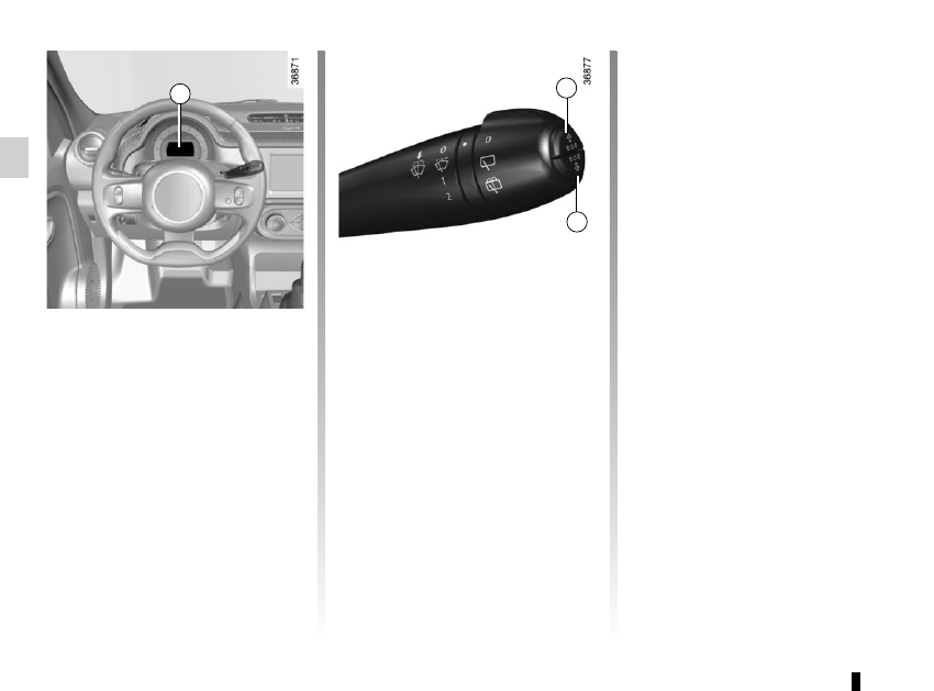
On-board computer 1

It includes the following functions:
– distance travelled;

– journey settings;
All these functions are described on the 

following pages.

Display selection keys 2 

and 3

Scroll through the following information 

upwards (key 2) or downwards (key 3

by pressing briefly and successively 

(the display depends on the vehicle 

equipment and country).
a)  total mileage recorder;
b)  trip mileage recorder;

c) fuel used;

d) average fuel consumption;

e) Current fuel consumption;

f) estimated range;

2

3

1

g) distance travelled since the last 

reset;

h) average speed;

i) mileage before next service/oil 

change;

j)  Reset the tyre pressure

k) cruise control/speed limiter pro-

grammed speed;

l) time;

m) temperature.

1.51

ON-BOARD COMPUTER: general information 

(2/2)

Resetting the trip mileage

With “trip mileage recorder” selected on 

the display, press button 2 or 3 until the 

mileage recorder resets to zero.

Resetting the journey 

parameters (reset button)

With one of the trip parameters selected 

as the display, press and hold button 2 

or 3 until the display resets.

Interpreting some of the 

values displayed after 

resetting

The values showing average fuel con-

sumption, range and average speed 

will become more stable and reliable 

the further you travel after pressing the 

reset button.
For the first few miles after pressing 

the reset key you will notice that the 

range increases as you travel. This 

range takes into account the average 

fuel consumption since the last time the 

reset button was pressed. Therefore, 

the average fuel consumption may de-

crease when:
–  

the vehicle stops accelerating;

–  

the engine reaches its operating 

temperature (if the engine was cold 

when the reset key was pressed);

–  

when driving from an urban area 

onto the open road.

Automatic resetting of the 

journey parameters

Resetting occurs automatically when 

the maximum value of any of the pa-

rameters is exceeded.

2

3

1.52

ON-BOARD COMPUTER: trip settings 

(1/4)

The display of information shown below DEPENDS ON THE VEHICLE EQUIPMENT AND COUNTRY.

Examples of selections

Interpreting the display selected

a) Total mileage recorder.

101778 km

b) Trip mileage recorder.

112.4 km

c) Trip settings.

Fuel used.

Fuel consumed since the last reset.

5.8 L/100

d) Average fuel consumption since the last reset.

The value is displayed after having travelled at least 400 metres since the last 

reset.

5.8 L/100

1.53

ON-BOARD COMPUTER: trip settings 

(2/4)

The display of information shown below DEPENDS ON THE VEHICLE EQUIPMENT AND COUNTRY.

Examples of selections

Interpreting the display selected

e) Current fuel consumption.

This value is displayed after a speed of approximately 20 mph (30 km/h) is 

reached.

7.4 L/100

f)  Estimated range with remaining fuel.

The value is displayed after driving 400 metres.

541 km

g) Distance travelled since last reset.

522 km

h) Average speed since the last reset.

The value is displayed after driving 400 metres.

123.4 km/H

1.54

ON-BOARD COMPUTER: trip settings 

(3/4)

The display of information shown below DEPENDS ON THE VEHICLE EQUIPMENT AND COUNTRY.

Examples of selections

Interpreting the display selected

i)  Mileage before service or oil change.
Distance remaining until the next service (displayed in miles 

(kilometres) or days), then when the service nears, the 
warning light 

©

 is displayed on the instrument panel.

The vehicle requires a service as soon as possible.

Resetting: To reset the mileage before the next service/oil change, press and hold button 2 or  for approximately 10 seconds 

until the display shows the mileage before service/oil change without flashing.

1.55

The display of information shown below DEPENDS ON THE VEHICLE EQUIPMENT AND COUNTRY.

ON-BOARD COMPUTER: trip settings 

(4/4)

Examples of selections

Interpreting the display selected

 SET

j)  Reset the tyre pressure.

Please refer to the information on the “Tyre pressure loss
 warning” in Section 2.

90 km/H

k) Cruise control and speed limiter programmed speed.

Refer to the information on the “Speed limiter” and “Cruise control” in Section 2.

16:30

l) Time.

Please refer to the information on the “Clock and exterior temperature” in Section 1.

1.56

Wait a few seconds, the minutes will 

flash: repeatedly press or press and 

hold button 3 or 4 to set the time.
When setting is complete, the hours 

and minutes remain displayed continu-

ously for 5 seconds: your setting is reg-

istered.
You may change the display.

Display A

To access the display 2 for setting the 

time, press button 3 or 4 on the stalk 1.
Wait a few seconds; the hours and min-

utes will begin to flash. You are now in 

setting mode, press and hold button 3 

or 4 to set the hour.
Once the minutes flash, repeatedly 

press or press and hold button 3 ou 4 

to set the time.

CLOCK AND EXTERIOR TEMPERATURE 

(1/2)

3

4

If the power supply is cut (battery 

disconnected, supply wire cut, etc.), 

the clock must be reset.
We recommend that you do not 

adjust these settings while driving.

12:00

2

1

1

A

1.57

Display B

Vehicles fitted with touch-screen 

multimedia, navigation aid systems, 

telephones, etc.
Refer to the separate instructions for 

the function to understand the special 

features of this equipment.

External temperature 

indicator

Special note:
When the exterior temperature is - 3°C 

to + 3°C, the °C characters flash (sig-

nalling a risk of ice on the road).

External temperature in-

dicator
As ice formation is related 

to climatic exposure, local 

air humidity and temperature, the 

external temperature alone is not 

sufficient to detect ice.

CLOCK AND EXTERIOR TEMPERATURE 

(2/2)

If the power supply is cut (battery disconnected, supply wire cut, etc.), the clock 

must be reset.
We recommend that you do not adjust these settings while driving.

B

1.58

Daytime running lights 

function

(front lights only)
If fitted to the vehicle, the daytime 

running lights come on automatically 

when the engine is started or, depend-

ing on the vehicle, when the ignition is 

switched on.

EXTERIOR LIGHTING AND SIGNALS 

(1/3)

š

Side lights

Turn the ring 2 until the symbol 

is opposite mark 3.
An indicator light on the instrument 

panel will come on.

1

Before driving at night, check that the electrical equipment is operating 

correctly and adjust the headlight beams (if your vehicle is not carrying 

its normal load). As a general precaution, check that the lights are not ob-

scured (by dirt, mud, snow or objects being transported).

k

Dipped beam 

headlights

Manual operation
Turn the ring 2 until the symbol is oppo-

site mark 3. This indicator light on the 

instrument panel comes on.

Automatic operation

(depending on vehicle)
Turn ring 2 until the AUTO symbol is op-

posite mark 3: with the engine running, 

the dipped beam headlights switch on 

or off automatically depending on the 

brightness of the light outside, without 

any action on stalk 1.

When driving on the left in a left-

hand drive vehicle (or vice versa), 

drivers must re-adjust their lights 

throughout their stay (see “Adjusting 

headlight beams” in Section 1).

3

1

2

1.59

EXTERIOR LIGHTING AND SIGNALS 

(2/3)

Switching off the lights

There are two possibilities:

–  manually, move ring 2 to position 0;

– automatically, if the ring 2 is in 

AUTO position and if the main beam 

headlights are not switched on. The 

lights will go out automatically when 

the engine is switched off, the dri-

ver’s door is opened or the vehicle 

is locked. In this case, the next time 

the engine is started, the lights will 

be switched back on according to the 

position of the ring 2, taking into ac-

count the exterior light level, without 

moving the stalk 1.

Lights-on reminder buzzer

A warning beep sounds when the driv-

er’s door is opened to warn you that the 

lights are still on.

g

Front fog lights

Turn the centre ring 4 on the 

stalk  1 until the symbol is opposite 

mark 3, then release it.
Operation of the fog lights depends on 

the exterior lighting position selected, 

and an indicator light will light up on the 

instrument panel.

Cornering lights function

Whenever the dipped beam headlights 

are on and under certain conditions (at 

speed, the steering wheel at an angle, 

in forward gear, the indicator lights on, 

etc.), when taking a corner one of the 

front fog lights will come on to light the 

inside of the bend.

1

2

á

Main beam headlights

With the engine running and 

the dipped beam headlights on, push 

stalk 1. This indicator light on the instru-

ment panel comes on.

To return to the dipped headlight posi-

tion, pull stalk 1 towards you again.

4

3

1.60

EXTERIOR LIGHTING AND SIGNALS 

(3/3)

f

Rear fog light

Turn the centre ring 4 on 

the stalk until the symbol is opposite 

mark 3, then release it.
Depending on the vehicle, the stalk re-

turns to the initial position or stays in 

position.
Operation of the fog lights depends on 

the exterior lighting selected, and an in-

dicator light will light up on the instru-

ment panel.
To avoid inconveniencing other road 

users, remember to switch off the rear 

fog light when it is no longer needed.

Turning off the fog lights

There are two possibilities:

–  manually, depending on the vehi-

cle, turn the ring 4 again to bring the 

mark 3 opposite the symbol for the 

fog light that you want to switch off, 

or bring the ring 4 into position 0. The 

corresponding indicator light will go 

out on the instrument panel;

– the lights will go out automati-

cally when the engine is switched 

off or the vehicle is locked, and the 

fog lights when the driver’s door is 

opened.

The front and rear fog lights switch off 

when the exterior lights are switched 

off.

When driving in fog or snow, or 

when transporting objects which are 

higher than the roof, the headlights 

do not come on automatically.
Switching on the fog lights remains 

the responsibility of the driver: the 

indicator lights on the instrument 

panel inform you whether the fog 

lights are lit (indicator light on) or not 

(indicator light not on).

4

1

3

1.61

é

Hazard warning lights 

Press switch 2.

This switch activates all four direction 

indicators and the side indicator lights 

simultaneously. It must only be used in 

an emergency to warn drivers of other 

vehicles that you have had to stop in 

an area where stopping is prohibited or 

unexpected, or that you are obliged to 

drive under special conditions.

Depending on the vehicle, the hazard 

warning lights may come on auto-

matically under heavy deceleration. 

You can switch them off by pressing 

switch 2 once.

Direction indicators

Move stalk 1 parallel to the steering 

wheel and in the direction you are going 

to turn it.

One-touch mode
When driving, it is possible that the 

steering wheel may not be turned suf-

ficiently to return the stalk automatically 

to its starting position.

In this case, move the stick 1 to half-

way, then release it: it will return to its 

initial position and the indicator light 

flashes three times.

Horn

Press steering wheel boss A.

Headlight flasher

Pull stalk 1 towards you to flash the 

headlights.

AUDIBLE AND VISUAL SIGNALS

A

1

2

1.62

HEADLIGHT BEAM ADJUSTMENT 

(1/2)

On vehicles fitted with this function, 

control A allows you to adjust the height 

of the beams according to the load.
Turn control A downwards to lower the 

headlights and upwards to raise them.

Examples of positions for adjusting control A according to the load

0

Driver alone or with front passenger

1

All seats occupied

2

All seats occupied and the boot laden

3

Driver only with the boot laden

A

1.63

Once the adjustment has been done, 

make sure the bonnet is repositioned 

and closed properly.

HEADLIGHT BEAM ADJUSTMENT 

(2/2)

Temporary adjustment

Open the bonnet (please refer to the in-

formation on the “Bonnet” in Section  4) 

and slide it sideways to access the 

screw 1 and marking B.
Note: Take care not to scratch the vehi-

cle paintwork.
For each headlight, using a screw-

driver, turn the screw 1 by a quarter 

turn towards the - symbol to lower the 

beams.
Return to the starting point once your 

trip is over:  turn the screw 1 by a quar-

ter turn towards the + symbol to raise 

the beams.

B

1

When driving on the left in a left-hand 

drive vehicle (or vice versa), you must 

adjust your lights temporarily for the 

duration of your trip.

For your safety, do not 

remove the bonnet holding 

straps. Risk of the bonnet 

falling on the road surface.

1.64

With the ignition on, move stalk 1
–  A park.
–  B
 intermittent wiping.

Depending on the vehicle, the wipers 

may stop for a few seconds between 

wipes. It is possible to change the 

time between sweeps by turning 

ring 2.

–  C normal wiping speed.
–  D
 fast wiping speed.

Special note
When driving,
 the wiping speed slows 

down whenever the vehicle stops. For 

example: the speed will change from 

a fast wiping speed to normal wiping 

speed.

As soon as the vehicle moves off, 

wiping will return to the speed originally 

selected.

Any action on stalk 1 overrides and 

cancels automatic operation.
Starting the vehicle with the stalk in 

position  D triggers a slow continuous 

sweeping movement. Adjusting the 

stalk to position D is necessary to trig-

ger a rapid continuous sweeping move-

ment. 

Vehicles with automatic wiper 

function

With the engine running, move stalk 1
–  A park.
–  B
 automatic wiper function

When this position is selected, the 

system detects water on the wind-

screen and triggers the wipers at a 

suitable wiping speed:

–  E: minimum sensitivity

–  F: maximum sensitivity

NB: in foggy weather or during 

snowfalls, the wiping is not automati-

cally triggered and remains under 

the driver’s control.

–  C normal wiping speed.
–  D
 fast wiping speed.

WINDSCREEN WASH, WIPE 

(1/2)

A

B
C

D

1

1

Position C is accessible with the ig-

nition on. Positions B and D are ac-

cessible only with the engine run-

ning.

Positions BC and D are accessible 

with the ignition on.

E

F

2

1.65

Before any action involving 

the windscreen (washing 

the vehicle, de-icing, clean-

ing the windscreen, etc.) 

return stalk 1 to position A (park).
Risk of injury and/or damage.

Windscreen washer

With the ignition on, pull stalk 1 to-

wards you.
A brief pull will trigger a single sweep 

of the wipers, in addition to the wind-

screen washer.
A longer pull triggers, as well as the 

windscreen washer, continuous sweep-

ing until the end of the request, then 

three return sweeps, then after a few 

seconds, a fourth.

WINDSCREEN WASH, WIPE 

(2/2)

A

B

C

D

1

When working in the engine 

compartment, ensure that 

the windscreen wiper stalk 

is in position A (park).

Risk of injury.

Do not try to lift the wiper blades. 

They cannot remain detached from 

the windscreen. To replace the 

blades, refer to Section 5: “Wiper 

blades”.

Efficiency of a wiper blade

Check the condition of the wiper 

blades. How long they last depends 

on you:

–  it must remain clean: clean the 

blade and the screen regularly 

with soapy water;

–  do not use it when the screen is 

dry;

–  free it from the screen when it has 

not been used for a long time.

In all cases, replace it as soon as 

it begins to lose efficiency: approx-

imately once a year. Refer to the 

paragraph on “Wiper blades” in 

Section 5.

Precaution for using the 

wipers

– In freezing or snowy weather 

conditions, clear the screen 

before starting the wipers (risk of 

motor overheating);

–  ensure that no objects are ob-

structing the travel of the blade.


Content   ..  2  3  4  5   ..