Renault Megane (2018 year). Manual - part 18
 

  Index      Renault     Renault Megane - service manual 2018 year in english


Search            


Content   ..  16  17  18  19   ..


Renault Megane (2018 year). Manual - part 18


5.8

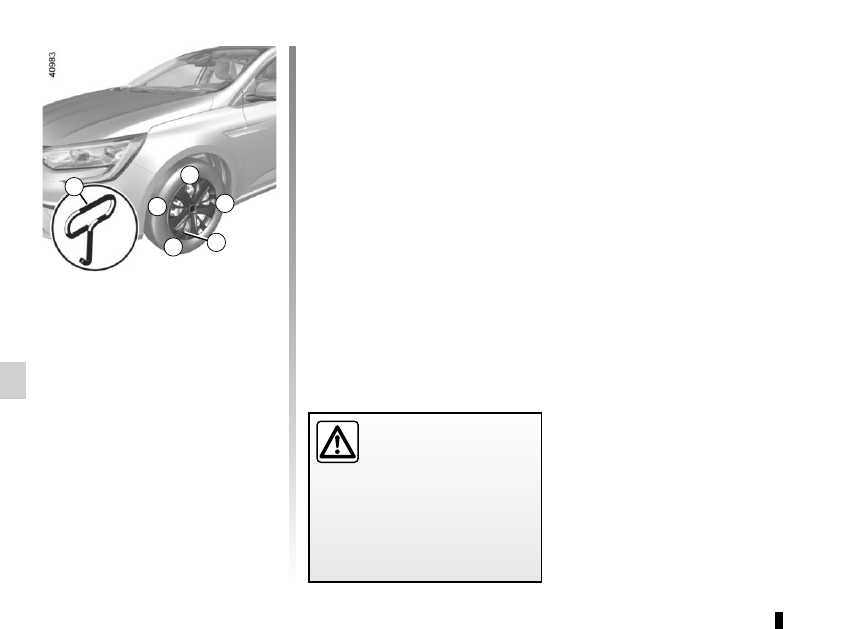
Remove using the hubcap tool 1 (lo-

cated in the tool kit) by connecting the 

hook in the recess provided next to the 

valve  (to attach the metal clip).
To refit it, align it with valve 2. Push the 

retaining hooks in fully, starting with 

side  A near the valve, followed by B 

and C, finishing at D opposite the valve.
Note: if you are using anti-theft bolts, 

refer to the information on “Changing a 

wheel”.

HUBCAP

Do not leave the tools un-

secured inside the vehicle 

as they may come loose 

under braking. After use, 

check that all the tools are correctly 

clipped into the tool kit, then posi-

tion it correctly in its housing: risk of 

injury.

1

2

A

B

D

C

5.9

CHANGING A WHEEL 

(1/2)

Place the jack 3 horizontally; the jack 

head must be lined up with the sill clos-

est to the wheel concerned, as shown 

by an arrow 1.
Crank up the jack by hand at first to 

align the base plate (which should be 

inclined further inwards than the jack 

head).
Turn the wheelbrace until the wheel lifts 

off the ground.

Switch on the hazard warn-

ing lights.
Keep the vehicle away from 

traffic and on a level surface 

where it will not slip.
Apply the parking brake and engage 

a gear (first or reverse, or P for auto-

matic transmissions).

Ask all the passengers to leave the 

vehicle and keep them away from 

traffic.

If the vehicle is parked on 

the hard shoulder, you must 

warn other road users of 

your vehicle’s presence 

with a warning triangle or with other 

devices as per the legislation apply-

ing to the country you are in.

If the vehicle is not equipped with a 

jack or wheelbrace, you can obtain 

these from your approved dealer.

Vehicles equipped with a jack 

and wheelbrace

If necessary, remove the wheel trim.
Use the wheelbrace 2 to slacken off the 

wheel bolts. Position it so as to be able 

to push from above.

3

2

1

5.10

Undo the bolts and take off the wheel.
Fit the emergency spare wheel onto 

the hub and rotate it until the mounting 

holes in the wheel coincide with those 

of the hub.
If bolts are supplied with the emergency 

spare wheel, only use these bolts for 

the emergency spare wheel. Tighten 

the bolts, checking that the wheel is 

correctly positioned on its hub and un-

screw the jack.
With the wheel on the ground, tighten 

the bolts fully and have the tightness of 

the bolts checked and the emergency 

spare wheel pressure checked as soon 

as possible.

Anti-theft bolt
If you use anti-theft bolts, fit these 

nearest the valve (wheel embel-

lisher may not be able to fit).

If you have a puncture, re-

place the wheel as soon as 

possible.
A tyre which has been punc-

tured should always be inspected 

(and repaired, where possible) by a 

specialist.

CHANGING A WHEEL 

(2/2)

5.11

TYRES 

(1/3)

Maintaining the tyres

The tyres must be in good condition 

and the tread form must have sufficient 

depth; tyres approved by our Technical 

Department have tread wear indica-

tors 1 which are indicators moulded 

into the tread at several points.

The tyres are the only contact between 

the vehicle and the road, so it is essen-

tial to keep them in good condition. 
You must make sure that your tyres 

con- form to local road traffic regula-

tions.

When the tread has worn down to the 

wear warning strips, these strips will 

become visible 2: it is then necessary 

to replace your tyres because the tread 

rubber is now only 1.6 mm deep at 

most, resulting in poor road holding 

on wet roads.
An overloaded vehicle, long journeys 

by motorway, particularly in very hot 

weather, or continual driving on poorly 

surfaced minor roads will lead to more 

rapid tyre wear and affect safety.

Incidents which occur when 

driving, such as striking the 

kerb, may damage the tyres 

and wheel rims, and could 

also lead to misalignment of the 

front or rear axle geometry. In this 

case, have the condition of these 

checked by an approved dealer.

2

1

5.12

TYRES 

(2/3)

Tyre pressures

Adhere to the tyre pressures (including 

the emergency spare wheel). The tyre 

pressures should be checked at least 

once a month and additionally before 

any long journey (refer to the label af-

fixed to the edge of the driver’s door).

The pressures should be checked cold: 

ignore higher pressures which may be 

reached in hot weather or following a 

high speed journey.
If the tyre pressures cannot be checked 

when the tyres are cold, increase the 

pressures from 0.2 to 0.3 bar (or 3 PSI).
Never deflate a hot tyre.

Special note

Depending on the vehicle, there may 

be an adapter which needs to be posi-

tioned on the valve before air is added.

Vehicle fitted with a tyre pressure 

monitoring system 
If under-inflated (puncture, low pressure 

etc.), the warning light 

 lights up 

on the instrument panel; please refer to 

“Tyre pressure monitoring system” in 

Section 2.

Emergency spare wheel

Refer to the information on “Puncture” 

and “Changing a wheel” in Section 5.

Changing wheels around

This practice is not recommended.

Incorrect tyre pressures 

lead to abnormal tyre wear 

and unusually hot running. 

These are factors which 

may seriously affect safety and lead 

to:
–  poor road holding,
–  risk of bursting or tread separa-

tion.

The pressure depends on the load 

and the speed of use. Adjust the 

pressure according to the condi-

tions of use (refer to the label affixed 

to the edge of the driver’s door).

Please be aware that a 

poorly tightened or miss-

ing valve cap can make the 

tyres less airtight and lead 

to pressure loss.
Always use valve caps identical to 

those fitted originally and tighten 

them fully.

5.13

Studded tyres
This type of equipment may only be 

used for a limited period and as laid 

down by local legislation. It is neces-

sary to observe the speed specified by 

current legislation.

These tyres must, at a minimum, be 

fitted to the two front wheels.
Chains
For safety reasons, fitting snow 

chains to the rear axle is strictly for-

bidden.
Chains cannot be fitted 
to tyres which 

are larger than those originally fitted to 

the vehicle.

TYRES 

(3/3)

Use in winter

Snow or Winter tyres
We would recommend that these be 

fitted to all four wheels to ensure that 

your vehicle retains maximum adhe-

sion. Warning: These tyres sometimes 

have a specific direction of rotation and 

a maximum speed index which may be 

lower than the maximum speed of your 

vehicle.

Snow chains may only be 

fitted to tyres of the same 

size as those originally 

fitted to your vehicle.

In all cases, we would recommend that you contact an authorised dealer who will 

be able to advise you on the choice of equipment which is most suitable for your 

vehicle.

Changing a wheel

As the tyre pressure moni-

tor may take several min-

utes to correctly determine 

the positions of the wheels and the 

pressure values after driving, check 

the tyre pressures following any op-

eration.

17” wheels and larger 

cannot be fitted with 

chains.
If you wish to use special 

equipment, please consult an au-

thorised dealer.

Fitting new tyres

For your safety, please re-

spect the speed limit.
When they need to be re-

placed, only tyres of the 

same make, size, type and profile 

should be used on a single axle.
They must: either have a load ca-

pacity and a speed capacity at 

least equal to the original tyres, 

or correspond to those recom-

mended by your authorised 

dealer.
Failure to heed these instructions 

could endanger your safety and 

affect your vehicle’s roadworthi-

ness.
Risk of loss of control of the ve-

hicle.

5.14

Any operation on (or modi-

fication to) the electrical 

system must be performed 

by an approved dealer 

since an incorrect connection might 

damage the electrical equipment 

(harness, components and in partic-

ular the alternator). In addition, your 

Dealer has all the parts required for 

fitting these units.

LED dipped beam 

headlights 1

Please see an authorised dealer.

LED main beam headlights 

Please see an authorised dealer.

FRONT HEADLIGHTS: replacing the bulbs 

(1/2)

Halogen dipped beam 

headlight

To change the bulb:

–  open the bonnet;

– remove cover B;

–  Turn the bulb holder a quarter 

turn 4;

–  remove the bulb.
Bulb type: H7.
Once the bulb has been replaced, 

check that it is properly secured.

B

A

The bulbs are under pres-

sure and can break when 

replaced.
Risk of injury.

1

Please note when work-

ing close to the engine that 

it may be hot. In addition, 

the engine cooling fan may 

start at any moment. The 


warning light in the engine compart-

ment reminds you of this.
Risk of injury.

2

5.15

To comply with local legislation, or 

as a precaution, you can obtain an 

emergency kit containing a set of 

spare bulbs and fuses from an ap-

proved dealer.

Daytime running lights and 

side lights 5

Please see an authorised dealer.

Front fog lights 7

–  Access the bulb holder via the un-

derneath of the vehicle;

–  unclip the access flap 8;

–  turn the bulb holder a quarter turn;

–  remove the bulb.
Type of bulb: H16.
Once the bulb has been replaced, 

check that it is properly secured.

Additional lights

If you wish to fit fog lights to your ve-

hicle, please see an authorised dealer.

FRONT HEADLIGHTS: replacing the bulbs 

(2/2)

Direction indicator light 6

–  Access the bulb holder via the un-

derneath of the vehicle;

–  unclip the access flap 8;

–  turn the bulb holder a quarter turn;

–  remove the bulb.
Type of bulb: PY21W.
Once the bulb has been replaced, 

check that it is properly secured.
However, we would advise you to have 

them replaced by an approved dealer if 

it proves difficult.

7

5

6

8

3

4

Halogen main beam headlight

To change the bulb:

–  open the bonnet;

– remove cover A;

–  pull the bulb holder 3;

–  remove the bulb.
Bulb type: H7.
It is essential to use anti-U.V. 55W 

bulbs so as not to damage the plastic 

on the headlights.
Do not touch the bulb glass. Hold it 

by its base.
When the bulb has been changed, 

make sure you refit the cover correctly.

6

7

8

5.16

REAR LIGHTS AND SIDE LIGHTS: replacing the bulbs 

(1/9)

5-door version

Side light 3

Consult an approved dealer.

2

Access to the bulb holders 6 

and 7

Open the boot, remove the cover 4 to 

access the screw 5 and undo it.
Remove the rear lights unit.

Direction indicator light 2

Turn bulb holder 7 a quarter of a turn  

and take out the bulb.
Bulb type: PY21W.

1

3

Brake light 1

Turn bulb holder 6 a quarter of a turn  

and take out the bulb.
Bulb type: P21W.
Refit the bulb holder and push the unit 

in fully until it locks in place.
Check that the light is properly locked 

in position.
Tighten the screw 5 and reposition the 

cover 4.

6

7

4

5

5.17

Reversing light

From the boot, unclip the cover on the 

interior trim of the boot lid 8 using a 

screwdriver or similar tool.

Turn bulb holder 9 a quarter of a turn  

and take out the bulb.
Bulb type: W16W.

Refitting
To refit, proceed in the reverse order, 

taking care not to damage the wiring.

The bulbs are under pres-

sure and can break when 

replaced.
Risk of injury.

REAR LIGHTS AND SIDE LIGHTS: replacing the bulbs 

(2/9)

9

8

High level brake light 10

Consult an approved dealer.

Rear fog lights 11

The front bumper needs to be removed; 

consult an authorised dealer.
Bulb type: P21W.

11

10

5.18

REAR LIGHTS AND SIDE LIGHTS: replacing the bulbs 

(3/9)

The bulbs are under pres-

sure and can break when 

replaced.
Risk of injury.

Side repeaters 13 and 

welcome lighting 14

The wing mirror needs to be removed; 

consult an authorised dealer.

13

Number plate lights 12

–  Unclip the light 12 using a tool such 

as a flat-blade screwdriver;

–  remove the light cover to gain access 

to the bulb.

Bulb type: W5W.

12

14

5.19

REAR LIGHTS AND SIDE LIGHTS: replacing the bulbs 

(4/9)

Estate version

Brake light 1

Consult an approved dealer

Side light 3

Consult an approved dealer.

Access to the bulb-holder 6

Open the luggage compartment lid, 

remove the cover 4 to access the two 

screws 5 and undo them.
Remove the rear lights unit.

Direction indicator light 2

Turn bulb holder 6 a quarter of a turn  

and take out the bulb.
Bulb type: PY21W.

6

4

5

1

2

3

5.20

Reversing light

From the boot, unclip the cover on the 

interior trim of the boot lid 7 using a 

screwdriver or similar tool.

Turn bulb holder 8 a quarter of a turn  

and take out the bulb.
Bulb type: W16W.

Refitting
To refit, proceed in the reverse order, 

taking care not to damage the wiring.

Rear fog light 10

The front bumper needs to be removed; 

consult an authorised dealer.
Bulb type: P21W.

REAR LIGHTS AND SIDE LIGHTS: replacing the bulbs 

(5/9)

8

7

Rear fog light 9

Unclip the flap located under the rear 

bumper using a flat-blade screwdriver 

or similar. Access the bulb holder, then 

unscrew it by turning towards the centre 

of the vehicle.
Bulb type: P21W.

High level brake light 11

Consult an approved dealer.

9

10

11

5.21

REAR LIGHTS AND SIDE LIGHTS: replacing the bulbs 

(6/9)

The bulbs are under pres-

sure and can break when 

replaced.
Risk of injury.

Side repeaters 13 and 

welcome lighting 14

The wing mirror needs to be removed; 

consult an authorised dealer.

13

Number plate lights 12

–  Unclip the light 12 using a tool such 

as a flat-blade screwdriver;

–  remove the light cover to gain access 

to the bulb.

Bulb type: W5W.

14

12

5.22

REAR LIGHTS AND SIDE LIGHTS: replacing the bulbs 

(7/9)

4-door version

Side light 3

Consult an approved dealer.

Access to the bulb holders 6 

and 7

Open the boot, remove the cover 4 to 

access the screw 5 and undo it.
Remove the rear lights unit.

Direction indicator light 2

Turn bulb holder 7 a quarter of a turn  

and take out the bulb.
Bulb type: PY21W.

4

5

Brake light 1

Turn bulb holder 6 a quarter of a turn  

and take out the bulb.
Bulb type: P21W.
Refit the bulb holder and push the unit 

in fully until it locks in place.
Check that the light is properly locked 

in position.
Tighten the screw 5 and reposition the 

cover 4.

6

7

1

2

3

5.23

Turn bulb holder 9 a quarter of a turn  

and take out the bulb.
Bulb type: W16W.

Refitting
To refit, proceed in the reverse order, 

taking care not to damage the wiring.

Reversing light

From the boot, unclip the cover on the 

interior trim of the boot lid 8 using a 

screwdriver or similar tool.

REAR LIGHTS AND SIDE LIGHTS: replacing the bulbs 

(8/9)

9

8

High level brake light 10

Consult an approved dealer.

Rear fog lights 11

The front bumper needs to be removed; 

consult an authorised dealer.
Bulb type: P21W.

11

10

The bulbs are under pres-

sure and can break when 

replaced.
Risk of injury.


Content   ..  16  17  18  19   ..