Dacia Pick-Up 1304/1305/1307. Service manual - part 37
IGNITION AND INJECTION
17
17 - 12
From now on, we can calculate the injection time (t
i
), the injection moment and the
ignition advance moment for each engine cycle.
The rotation sensor is fixed on the clutch case of the gearbox therefore it should be at 1
± 0,5 mm from the teeth peak of the flywheel.
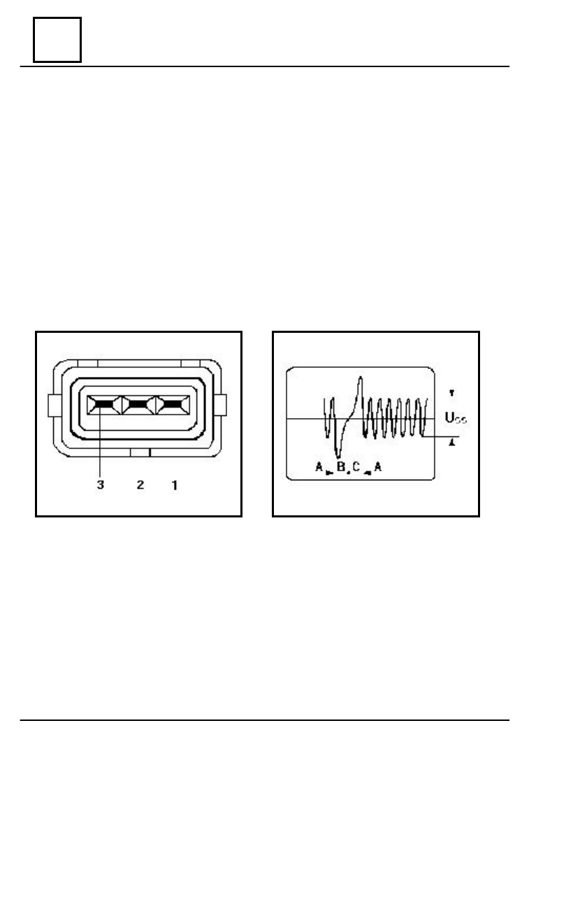
The connector for the rotation sensor has the following connections (drawing 8):
1,2 – capture of rotation signal
3 – screening
The sensor functioning can be checked by connecting the connector pins 1 and 2 or the
computer pins 3 and 21 to an oscilloscope. A good sensor will generate a signal shaped as
in drawing 8, during the engine functioning, in which we can identify the following:
A = gear toothed area (rotation signal)
B = the 2 missing teeth area
C = the first tooth area (reference signal)
The rotation sensor is not to be repaired but replaced.
Fig. 8
Fig.9
The rotation signal level should be Uss > 2,5 V, otherwise the engine won’t start.
The reference value R
1-2
= 650 – 1100 Ù at an environmental temperature of 20°C.
DESCRIPTION OF THE SYSTEM