Peugeot 1007 Dag (2005.5). Manual - part 11
 

  Index      Peugeot     Peugeot 1007 Dag 2005.5 - service manual in english


Search            


Content   ..  9  10  11  12   ..


Peugeot 1007 Dag (2005.5). Manual - part 11


150 - Checks

01-10-2005

151

-

Checks

01-10-2005

CHECKING THE LEVELS

Oil level

Check the level regularly and top up 

between  changes.  The  maximum 

consumption  is  0.5 l  per  600 miles 

(1 000 km).

Check  the  level  with  the  vehicle 

level, engine cold, using the oil level 

gauge on the instrument panel or the 

dipstick. 

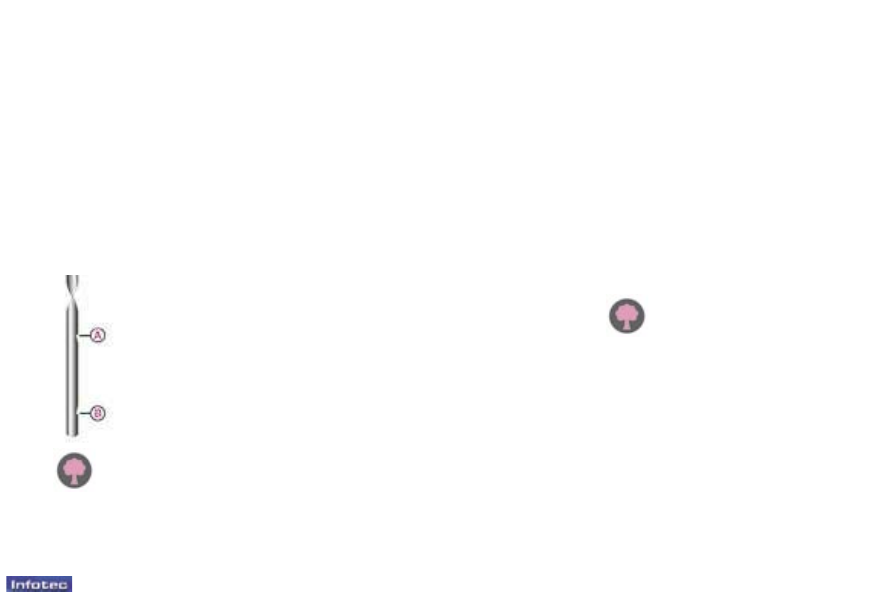
There  are  two  marks  on 

the dipstick:

A = maximum

Never ill past this mark.

B = minimum

Dipstick

Oil change

According to the information given in 

the servicing booklet.

Changing the brake luid

The brake luid must be changed at 

the intervals stated, according to the 

manufacturer's servicing schedule.

Use  luids  recommended  by  the 

manufacturer,  which  fulil  DOT4 

standards.

Windscreen and headlamp* 

wash level

For  best  quality  cleaning  and  for 

your  safety,  we  would  advise  that 

you  use  products  recommended  by 

PEUGEOT.

* According to country.

Viscosity selection

In all cases, the oil selected must meet 

the manufacturer's requirements.

Cooling system

Use  the  luid  recommended  by  the 

manufacturer.

When  the  engine  is  warm,  the  tem-

perature  of  the  coolant  is  controlled 

by the engine fan. As this fan can op-

erate  with  the  ignition  key  removed 

and  because  the  cooling  system  is 

pressurised,  wait  for  at  least  one 

hour  after  the  engine  has  stopped 

before carrying out any work.

Slacken  the  cap  by  two  turns  to  re-

lease  the  pressure  to  prevent  any 

risk  of  scalding.  When  the  pressure 

has  dropped,  remove  the  cap  and 

top up the level.

Note:  the  coolant  does  not  need  to 

be changed.

Used oil

Avoid  prolonged  contact  of  used  oil 

with the skin.

Brake  luid  is  harmful  to  health  and 

very corrosive.

To  maintain  the  reliability  of 

engines and emission control 

systems, the use of additives 

in engine oil is prohibited.

Do  not  dispose  of  used  oil, 

brake  luid  or  coolant  into 

drains or into the ground.

150 - Checks

01-10-2005

151

-

Checks

01-10-2005

CHECKS

Oil ilter

Change the ilter regularly, in accord-

ance with the servicing schedule.

Only  use  products  recom-

mended  by  PEUGEOT 

or  products  of  equivalent 

quality and characteristics.

To  ensure  best  perform-

ance from components as important 

as  the  braking  system,  PEUGEOT 

selects  and  offers  quite  speciic 

products.

To  prevent  damage  to  the  electrical 

units, avoid washing the engine. 

To check the main levels and cer-

tain  components,  in  accordance 

with the manufacturer's servicing 

schedule,  refer  to  the  pages  of 

the servicing booklet which corre-

spond to your vehicle's engine.

Battery

At the start of winter, have your bat-

tery checked by a PEUGEOT dealer.

Air ilter and passenger

compartment ilter

Have  the  ilter  elements  replaced 

regularly.

  If  you  drive  in  dusty 

conditions, change them twice as 

often.

Brake pads

Brake pad wear depends on the style 

of  driving,  in  particular  for  vehicles 

which  are  used  in  town,  over  short 

distances.


Handbrake

Where  the  handbrake  travel  is  too 

great  or  there  is  a  reduction  in  the 

performance  of  the  system,  the 

handbrake should be adjusted, even 

between services.

Have  the  system  checked  by  a

PEUGEOT dealer.

Manual gearbox

This does not require an oil change. 

Have  the  level  checked  in  accord-

ance with the manufacturer's servic-

ing schedule.

It  may  be  necessary  to 

check  the  thickness  of  the 

pads,  even  between  serv-

ices.

152 - Practical information

01-10-2005

153

-

Practical information

01-10-2005

Parking the vehicle

-  If possible, park the vehicle on lev-

el, stable and non-slippery ground.

-  Apply the handbrake, switch off the 

ignition and engage irst or reverse 

gear  (position 

R  for  the  "2 Tronic" 

gearbox).

CHANGING A WHEEL

Tools provided*

The  jack  and  the  chock  are  stored 

in  a  box  in  the  centre  of  the  spare 

wheel.

The other tools are stored in a case 

in the left boot trim.

1.  Jack.

2.  Chock.

3.  Wheelbrace.

4.  Extension.

5.  Wheel trim removal tool.

6.  "Bolt cover" tool.

7.  Centring guide.

8.  Removable towing eye.

Note:  if  your  vehicle  is  itted  with  a 

towbar,  the  jack  is  stored  in  the  left 

storage tray.

Access to the spare wheel and 

the jack

The wheel is located outside the ve-

hicle, under the rear loor, supported 

by a metal carrier.

-  Unclip the cover to gain access to 

the  spare  wheel  carrier  retaining 

bolt, located on the inside near the 

closing system.

-  Using  the  wheelbrace 

3  and  the 

extension 

4,  slacken  the  spare 

wheel carrier retaining bolt.

-  Lift the carrier to release the hook 

rearwards, then lower it.

-  Remove the spare wheel, then the 

jack 

1  and  the  chock  2  located  in 

the box.

* According to version.

152 - Practical information

01-10-2005

153

-

Practical information

01-10-2005

Removing a wheel

-  Place  the  chock 

2  at  the  rear  of 

the  wheel  diagonally  opposite  the 

wheel to be changed.

-  Remove  the  wheel  trim,  using  the 

wheelbrace 

3 (large model) or the 

wheel  trim  removal  tool 

5  (small 

model), by pulling at the valve pas-

sage hole.

-  Remove  the  chrome-plated  bolt 

covers  and  the  plastic  cover  from 

the bolts using the "bolt cover" tool 

(Special features of alloy wheels).

-  Slacken the wheel bolts.

-  Place  the  jack 

1  under  one  of  the 

four  locating  points  on  the  sub-

frame 

A closest to the wheel to be 

changed.  Ensure  that  the  entire 

surface of the jack base plate is in 

contact with the ground.

-  Extend the jack, completely unscrew 

the bolts and remove the wheel.

Reitting the wheel

-  Position  the  wheel  using  the  cen-

tring guide 

7.

-  Lightly  pre-tighten  the  bolts  using 

the wheelbrace 

3.

-  Compress the jack 

and release it.

-  Fully  tighten  the  bolts  using  the 

wheelbrace.

-  Replace  the  trim,  starting  at  the 

valve passage hole, and press it on 

using the palm of the hand.

For your safety, always 

change a wheel:

-  on  level,  stable  and  non-slippery 

ground,

-  with the handbrake applied,

-  with  irst  or  reverse  gear  engaged 

(position 

for the "2 Tronic" gear-

box),

-  with the vehicle chocked,

-  never go underneath a vehicle raised 

using a jack (use an axle stand).

-  Do  not  forget  to  fully  tighten  the 

spare wheel carrier retaining bolt.

-  Stow the tools in the case, then put 

it back in the left boot trim.

Replacing the wheel in the 

carrier

-  Replace the jack 

and the chock 

in the box.

-  Replace the wheel in the carrier.

-  Lift the wheel then the carrier and 

reposition the hook.

After changing the wheel

-  Have  the  tightening  of  the  bolts 

and the pressure of the spare tyre 

checked as soon as possible by a 

PEUGEOT dealer.

-  Do  not  exceed  its  maximum  au-

thorised speed: 50 mph (80 km/h).

-  Have  the  punctured  tyre  repaired 

and  replace  it  on  the  vehicle  as 

soon as possible.

-  15  and  16  inch  punctured  wheels 

cannot be placed in the carrier.

154 - Practical information

01-10-2005

155

-

Practical information

01-10-2005

Special features of alloy 

wheels

Bolt covers

Alloy  wheel  bolts  are  covered  by 

chrome trims.

Use the yellow tool

 6 to remove the 

trims before slackening the bolts.

Fitting the spare wheel

If  your  vehicle  is  itted  with  a  steel 

spare  wheel,  when  itting  it,  it  is 

normal when tightening the bolts to 

notice that the washers do not come 

into  contact  with  the  rim. The  spare 

wheel is secured by the cone shape 

of each bolt. 

Anti-theft bolts

If  your  wheels  are  itted  with  an 

anti-theft  bolt  (one  per  wheel),  the 

chrome  trim  and  then  the  plastic 

cover must be removed using yellow 

tool 

6,  before  unscrewing  the  bolt 

using  the  anti-theft  socket  and  the 

wheelbrace.

Note: the anti-theft socket was given 

to  you  on  delivery  of  your  vehicle 

along with the duplicate keys and the 

conidential card.

Make  a  careful  note  of  the  code 

number engraved on the head of the 

anti-theft socket. This will enable you 

to  obtain  duplicate  sockets  from  a 

PEUGEOT dealer.

Fitting snow tyres

If you it snow tyres mounted on steel 

wheels  onto  your  vehicle,  it  is 

es-

sential to use special bolts available 

from your PEUGEOT dealer. 

Wheels equipped with 195/50 R 16 

tyres  cannot  be  itted  with  snow 

chains.

For further information, contact a 

PEUGEOT dealer.

154 - Practical information

01-10-2005

155

-

Practical information

01-10-2005

CHANGING A BULB

Front lights

1 -  Side lights (W 5 W)

-  Remove the plastic cover 

A.

-  Remove the bulb holder.

-  Remove the bulb and change it.

2 -  Dipped beam headlamps/Main 

beam headlamps 

(H4-60/55 W)

-  Remove the plastic cover 

B.

-  Disconnect the connector.

-  Push the spring 

towards the right, 

as indicated on the headlamp.

-  Remove and replace the bulb.

3 -  Direction indicators 

(PY 21 W amber)

-  Turn the bulb holder 

a quarter of 

a turn and remove it. 

-  Turn the bulb a quarter of a turn.

-  Remove the bulb and change it.

In  certain  weather  condi-

tions  (low  temperatures, 

humidity), 

the  presence 

of  condensation  on  the 

inside  of  the  headlamp  glass  is 

normal; it disappears a few minutes 

after  the  lights  have  been  switched 

on.

156 - Practical information

01-10-2005

157

-

Practical information

01-10-2005

Only  use  H4  bulbs  manu-

factured by:

- GE/TUNGSRAM.

- PHILIPS,

- OSRAM,

to avoid damaging the headlamps.

Direction indicator side repeaters 

(WY 5 W amber)

-  Push  the  repeater  cover  forwards 

and release it.

-  Remove  the  repeater  and  change 

it.

Contact  a  PEUGEOT  dealer  to 

obtain a new bulb. 

4 -  Front fog lamps (H1-55 W)

-  Open  the  lap,  located  under  the 

mud  guard,  to  gain  access  to  the 

screw.

-  Remove the screw.

-  Push  the  assembly  outwards  to 

extract it.

-  Disconnect the connector.

-  Turn the protective cover 

A a quarter 

of a turn.

-  Disconnect the connector 

B.

-  Move aside the springs 

C.

-  Remove the bulb and change it.

To reit, proceed in the reverse order 

to removal.

It is 

essential that the lap is closed.

Amber 

coloured 

bulbs 

(direction  indicators  and 

side repeaters) must be re-

placed by bulbs of identical 

speciication and colour.

These meet the anti-UV (ultra-violet) 

speciications necessary for the cor-

rect  operation  and  reliability  of  the 

headlamps.

The headlamps are itted with a poly-

carbonate lens coated with a protec-

tive varnish. You are strongly advised 

to avoid cleaning them using a dry or 

abrasive  cloth  and  using  detergent 

products or solvents.

Use  a  soft,  damp  cloth  with  soapy 

water.

156 - Practical information

01-10-2005

157

-

Practical information

01-10-2005

Rear lights

1 -  Brake/side lights 

(P 21 W/5 W).

2 -  Direction indicators 

(P 21 W).

3 -  Reversing light 

(P 21 W), right side.


Fog lamp (P 21 W), left side.

These  4  bulbs  are  changed  by  re-

moving the light:
F

 Remove  the  access  lap  in  the 

corresponding  boot  side  trim  to 

access the light,

F

 Remove  the  two  light  ixing  nuts 

inside the boot,

F

 Unclip the harness,

F

 Remove the light pressing on the 

retaining tabs,

F

 Remove the seal,

F

 Remove  the  bulb  holder  moving 

aside the two tabs 

A,

F

 Turn the bulb a quarter of a turn,

F

 Remove the bulb and change it.

Note:  if  necessary,  use  the  wheel-

brace to remove the nuts.

When  reitting,  proceed  in  the  re-

verse order and take care to position 

the bulb holder, the seal and the light 

correctly.

Third brake light

(4 W 5 W bulbs)

F

 Using  a  10  mm  box  spanner, 

unscrew the 2 ixing nuts 

A.

F

 Release the lamp unit by pushing 

it outwards.

F

 Disconnect the connector and the 

rear wash-wipe pipe.

F

 Turn the bulb holder a quarter of a 

turn and remove it.

F

 Remove the bulb and change it.

When  reitting,  proceed  in  the  re-

verse order and ensure that the lamp 

unit  seal  and  the  rear  wash-wipe 

pipe  have  been  put  back  in  place 

correctly.

Do not tighten the nuts more than is 

necessary at the risk of breaking the 

light.

Number plate lights (W 5 W)

F

 Insert a thin screwdriver into one 

of the external holes of the lens.

F

 Push it outwards to unclip it.

F

 Remove the lens.

F

 Remove the bulb and change it. 

158 - Practical information

01-10-2005

159

-

Practical information

01-10-2005

CHANGING A FUSE

The  fuse  boxes  are  located  under 

the  fascia  on  the  left-hand  side  and 

in  the  engine  compartment  next  to 

the battery.

Correct

Removing and fitting a fuse

Before changing a fuse you must ind 

out the cause of the fault and have it 

put right. The fuse numbers are indi-

cated on the fuse box.
F

 Use the pliers 

A.

Incorrect

Pliers A

* The  maxi  fuses  provide 

additional  protection  for 

the electrical systems. All 

work must be carried out 

by a PEUGEOT dealer.

Fascia fuse box

F

 Turn the screw a quarter of a turn, 

then tilt the cover to open it.

F

 Turn the lever a quarter of a turn, 

then push and tilt the box to gain 

access to the fuses.

The  pliers 

A and the spare fuses B 

are ixed on the inside of the cover.

Fuse N°

Rating

Functions

FH1*

40 A

Left "Sesame" door.

FH2*

40 A

Right "Sesame" door.

FH3*

20 A

Heated seats.

FH4*

20 A

Audio ampliier.

FH5*

-

Not used.

Always  replace  a  faulty 

fuse with one of the same 

rating.

160 - Practical information

01-10-2005

161

-

Practical information

01-10-2005

Engine compartment fuse box

F

 Unclip the cover to gain access to 

the fuses.

Your vehicle's electrical sys-

tem  is  designed  to  operate 

with  standard  or  optional 

equipment.

Before  installing  other  electrical 

equipment  or  accessories  on  your 

vehicle, contact a PEUGEOT dealer.

Some  electrical  accessories  or  the 

way in which they are itted may have 

damaging effects on the operation of 

your vehicle (audio, control and elec-

trical load circuits).

PEUGEOT will not accept responsi-

bilty for the cost incurred in repairing 

your vehicle or for rectifying malfunc-

tions resulting from the installation of 

auxiliary  accessories  not  supplied 

and not recommended by PEUGEOT 

and not installed in accordance with 

its  instructions,  in  particular  where 

the equipment in question consumes 

more than 10 milliamperes.

* The  maxi  fuses  provide  additional 

protection  for  the  electrical  sys-

tems. All work must be carried out 

by a PEUGEOT dealer.

Fuse N°

Rating

Functions

MF1*

30 A

Fan assembly.

MF2*

30 A

ABS/ESP control unit.

MF3*

30 A

ABS/ESP control unit.

MF4*

60 A

Built-in Systems Interface supply.

MF5*

70 A

Built-in Systems Interface supply.

MF6*

80 A

Left and right "Sésame" doors - 

Audio ampliier - Heated seats.

MF7*

30 A

Ignition switch, power.

MF8*

80 A

Electric power steering.

Once the work has been carried out, 

close the cover very carefully.

160 - Practical information

01-10-2005

161

-

Practical information

01-10-2005

Fuse N°

Rating

Functions

1

10 A

Pre-heat unit (Diesel) - Water in diesel sensor (Diesel) - Reversing light - 

"2 Tronic" gearbox control unit.

2

15 A

Fuel pump.

3

10 A

ABS/ESP control unit.

4

10 A

Injection and power steering control units - Brake and clutch switches - 

"2 Tronic" gearbox relay - Additional heating unit (Diesel) - 

Engine coolant level detector (Diesel).

5

-

Not used.

6

15 A

Front fog lamps.

7

20 A

Headlamp wash pump.

8

20 A

Fan assembly relay - Injection control unit.

9

15 A

Left dipped headlamp.

162 - Practical information

01-10-2005

163

-

Practical information

01-10-2005

Fuse N°

Rating

Functions

10

15 A

Right dipped headlamp.

11

10 A

Left main beam headlamp.

12

10 A

Right main beam headlamp.

13

15 A

Horn.

14

10 A

Front and rear wash-wipe pumps.

15

30 A

Ignition coil (petrol) - Solenoid valves - Purge canister (petrol) - 

Oxygen sensors (petrol) - Injectors (petrol) - Air low sensor (Diesel) - 

Injection pump (Diesel) - Diesel high pressure regulation (Diesel).

16

30 A

Air pump relay - Diesel heater (Diesel).

17

30 A

Windscreen wipers.

18

40 A

Air blowers.

158 - Practical information

01-10-2005

159

-

Practical information

01-10-2005

CHANGING A FUSE

The  fuse  boxes  are  located  under 

the  fascia  on  the  left-hand  side  and 

in  the  engine  compartment  next  to 

the battery.

Correct

Removing and fitting a fuse

Before changing a fuse you must ind 

out the cause of the fault and have it 

put right. The fuse numbers are indi-

cated on the fuse box.
F

 Use the pliers 

A.

Incorrect

Pliers A

* The  maxi  fuses  provide 

additional  protection  for 

the electrical systems. All 

work must be carried out 

by a PEUGEOT dealer.

Fascia fuse box

F

 Turn the screw a quarter of a turn, 

then tilt the cover to open it.

F

 Turn the lever a quarter of a turn, 

then push and tilt the box to gain 

access to the fuses.

The  pliers 

A and the spare fuses B 

are ixed on the inside of the cover.

Fuse N°

Rating

Functions

FH1*

40 A

Left "Sesame" door.

FH2*

40 A

Right "Sesame" door.

FH3*

20 A

Heated seats.

FH4*

20 A

Audio ampliier.

FH5*

-

Not used.

Always  replace  a  faulty 

fuse with one of the same 

rating.

158 - Practical information

01-10-2005

159

-

Practical information

01-10-2005

Fuse N°

Rating

Functions

1

15 A

Diagnostic socket supply - Motorised strikers - "Sesame" door switches - 

Steering wheel controls.

4

20 A

Clock - Multifunction display - Audio equipment - Audio/telephone - Alarm unit.

5

15 A

Alarm siren. 

6

10 A

Diagnostic socket - Steering wheel angle sensor - Seat belt buckles control unit.

7

15 A

Alarm unit - Rain/brightness sensor.

9

30 A

Towbar socket.

10

40 A

Rear screen and exterior mirrors demisting.

11

15 A

Rear wiper.

12

30 A

Electric windows - Sunroof.

14

10 A

Engine fuse box - Steering wheel controls - Air bags and pre-tensioners control unit.

15

15 A

Instrument panel - Multifunction display - Audio equipment - Audio/telephone - 

CD changer - Air conditioning - Parking assistance - "Sesame" doors.

16

30 A

Central locking - Deadlocking.

20

10 A

Right brake light.

21

15 A

Left brake light - Third brake light.

22

20 A

Courtesy light - Map reading lights - Glove box light - Lighter - Electric exterior mirrors - 

Factory-itted equipment for audio equipment - Number plate lights.

SH

-

PARC shunt.

162 - Practical information

01-10-2005

163

-

Practical information

01-10-2005

CHANGING A WINDSCREEN 

WIPER BLADE

Placing the wiper blades in the 

special position
F

 Less than a minute after switching 

off the ignition, operate the wipers 

stalk to position the wiper blades 

in the centre of the windscreen.

Changing a front wiper blade
F

 Lift the wiper arm.

F

 Unclip the blade and remove it.

F

 Fit the new blade.

F

 Push back the wiper arm.

Note: the shortest blade is itted on 

the right-hand wiper arm.

To  return  the  windscreen  wipers 

to their normal position, switch on 

the ignition and operate the wipers 

stalk.

Changing the rear wiper blade
F

 Lift the wiper arm.

Unclip the blade and remove it.

F

 Fit the new blade.

Push back the wiper arm.

ECONOMY MODE FUNCTION

After  the  engine  has  stopped,  with 

the  key  in  the  accessories  position, 

certain  functions  (doors,  windscreen 

wipers,  electric  windows,  courtesy 

lights, audio equipment, etc.) can only 

be used for a cumulative duration of 

thirty minutes, to prevent discharging 

of the battery.

Once  the  thirty  minutes  are  over,  a 

message informing you of the switch 

to  economy  mode  appears  on  the 

multifunction  display  and  the  active 

functions are put on standby.

To resume the use of these functions 

immediately, start the engine and let 

it run for a few seconds.

A  lat  battery  will  prevent 

the engine from starting.

FITTING/REMOVING 

THE MAT*

When removing the mat on the driver's 

side, push the seat as far back as pos-

sible and remove the ixings.

When  reitting,  position  the  mat 

correctly  on  the  pins  and  clip  the 

ixings. 

Check  that  the  mat  is  secured  cor-

rectly.

To  prevent  the  mat  from  becoming 

caught under the pedals:

-  only use mats suited to the ixings 

already present in the vehicle.

It is imperative that these ixings are 

used.

-  never it one mat on top of another.

* According to version.

164 - Practical information

01-10-2005

165

-

Practical information

01-10-2005

RUNNING OUT OF FUEL 

(DIESEL)

If  you  should  run  out  of  fuel,  it  is 

necessary to re-prime the circuit:

-  ill  the  fuel  tank  with  at  least  ive 

litres of diesel,

-  squeeze  and  release  the  manual 

re-priming pump, under the bonnet 

under the protective cover, until fuel 

appears in the transparent pipe,

-  operate the starter until the engine 

starts.

BATTERY

To charge the battery using a 

battery charger:

-  Disconnect the battery,

-  Follow  the  instructions  for  use 

given by the battery charger manu-

facturer,

-  Reconnect  starting  with  the  nega-

tive (-) terminal,

-  Check  that  the  terminals  and  con-

nectors are clean. If they are covered 

with  sulphate  (white  or  greenish 

deposit), disconnect them and clean 

them.

The batteries contain harm-

ful substances such as sul-

phuric acid and lead. They 

must be disposed of in ac-

cordance  with  regulations  and  must 

never  be  discarded  with  household 

waste.

Take  used  remote  control  and  vehi-

cle  batteries  to  a  special  collection 

point.

To start the vehicle from 

another battery:

-  Connect the red cable to the posi-

tive (+) terminals of the two batter-

ies,

-  Connect  one  end  of  the  green  or 

black cable to the negative (-) ter-

minal of the slave battery 

B,

-  Connect the other end of the green 

or  black  cable  to  an  earth  point 

C 

on the broken down vehicle as far 

as possible from the battery,

-  Operate  the  starter,  let  the  engine 

run,

-  Wait for the engine to return to idle, 

then disconnect the cables.

Before  disconnecting  the 

battery,  you  must  wait  for 

2 minutes  after  switching 

off the ignition.

Never  disconnect  a  terminal  when 

the engine is running.

Never  charge  a  battery  without  irst 

disconnecting the terminals.

Close the windows, the sunroof and 

the  doors  before  disconnecting  the 

battery.  If  they  do  not  operate  nor-

mally  following  reconnection  of  the 

battery,  they  must  be  reinitialised 

(see  sections  "Sesame  doors"  and 

"Sunroof").

After  every  reconnection  of  the  bat-

tery,  switch  on  the  ignition  and  wait 

1 minute before starting to allow the 

electronic systems to be initialised. If 

slight dificulties are experienced af-

ter this, please contact a PEUGEOT 

dealer.

A.  Flat battery

B.  Slave battery

C.  Metal point (earth) on the bro-

ken down vehicle

It  is  advisable  to  discon-

nect  the  battery  if  the 

vehicle is not to be used 

for a period of more than 

one month.


Content   ..  9  10  11  12   ..