Nissan Pathfinder (2007 year). Instruction - part 400
TROUBLE DIAGNOSIS FOR SYSTEM
TF-81
[ATX14B]
C
E
F
G
H
I
J
K
L
M
A
B
TF
2007 Pathfinder
2.
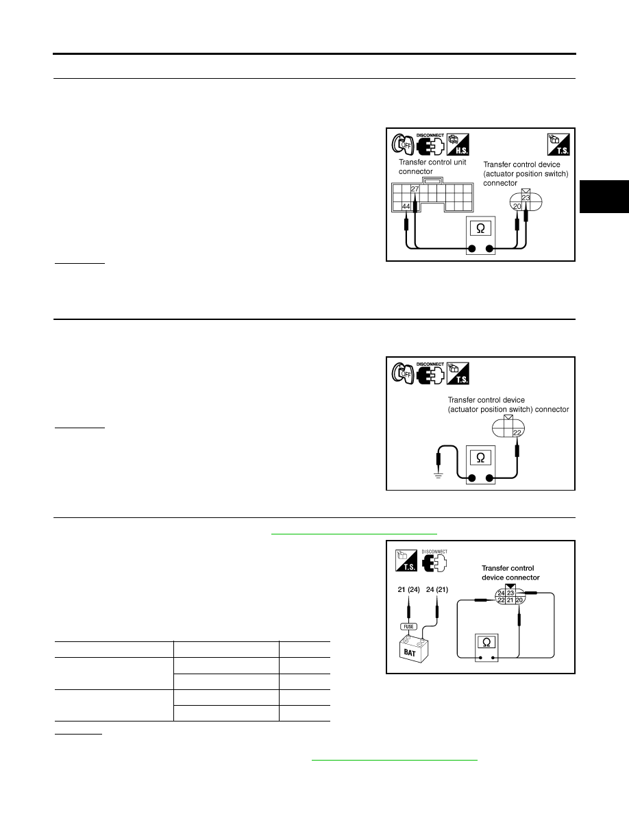
CHECK HARNESS BETWEEN TRANSFER CONTROL UNIT AND ACTUATOR POSITION SWITCH
1.
Turn ignition switch “OFF”. (Stay for at least 5 seconds.)
2.
Disconnect transfer control unit harness connector and the transfer control device (actuator position
switch) harness connector.
3.
Check continuity between the following terminals.
–
Transfer control unit harness connector M153 terminal 27 and
transfer control device (actuator position switch) harness con-
nector F58 terminal 23.
–
Transfer control unit harness connector M153 terminal 44 and
transfer control device (actuator position switch) harness con-
nector F58 terminal 20.
Also check harness for short to ground and short to power.
OK or NG
OK
>> GO TO 3.
NG
>> Repair or replace damaged parts.
3.
CHECK GROUND CIRCUIT
1.
Turn ignition switch “OFF”. (Stay for at least 5 seconds.)
2.
Disconnect transfer control device (actuator position switch) harness connector.
3.
Check continuity between transfer control device (actuator posi-
tion switch) harness connector F58 terminal 22 and ground.
Also check harness for short to power.
OK or NG
OK
>> GO TO 4.
NG
>> Repair open circuit or short to power in harness or con-
nectors.
4.
CHECK ACTUATOR POSITION SWITCH
1.
Remove transfer control device. Refer to
TF-138, "Removal and Installation"
2.
Check operation by applying battery voltage to transfer control
device (actuator motor) terminals 21 and 24.
CAUTION:
●
Do not operate actuator motor for more than 1 second.
●
Change the actuator motor position to “HIGH” when
installing.
●
Be careful not to overheat the harness.
OK or NG
YES
>> GO TO 5.
NO
>> Replace transfer control device. Refer to
TF-138, "Removal and Installation"
Continuity should exist.
SDIA2716E
Continuity should exist.
SDIA2717E
Terminal
Continuity
Continuity
24 (Battery voltage) - 21
(Ground)
20 - 22
YES
22 - 23
NO
21 (Battery voltage) - 24
(Ground)
22 - 23
YES
20 - 22
NO
LDIA0101E