Nissan Qashqai (2007-2010). Manual - part 926
HAC-64
< COMPONENT DIAGNOSIS >
[AUTOMATIC AIR CONDITIONER]
BLOWER MOTOR
9.
CHECK BLOWER MOTOR FEEDBACK SIGNAL
1.
Reconnect fan control amp. connector.
2.
Turn ignition switch ON.
3.
Turn fan control dial to 1st speed.
4.
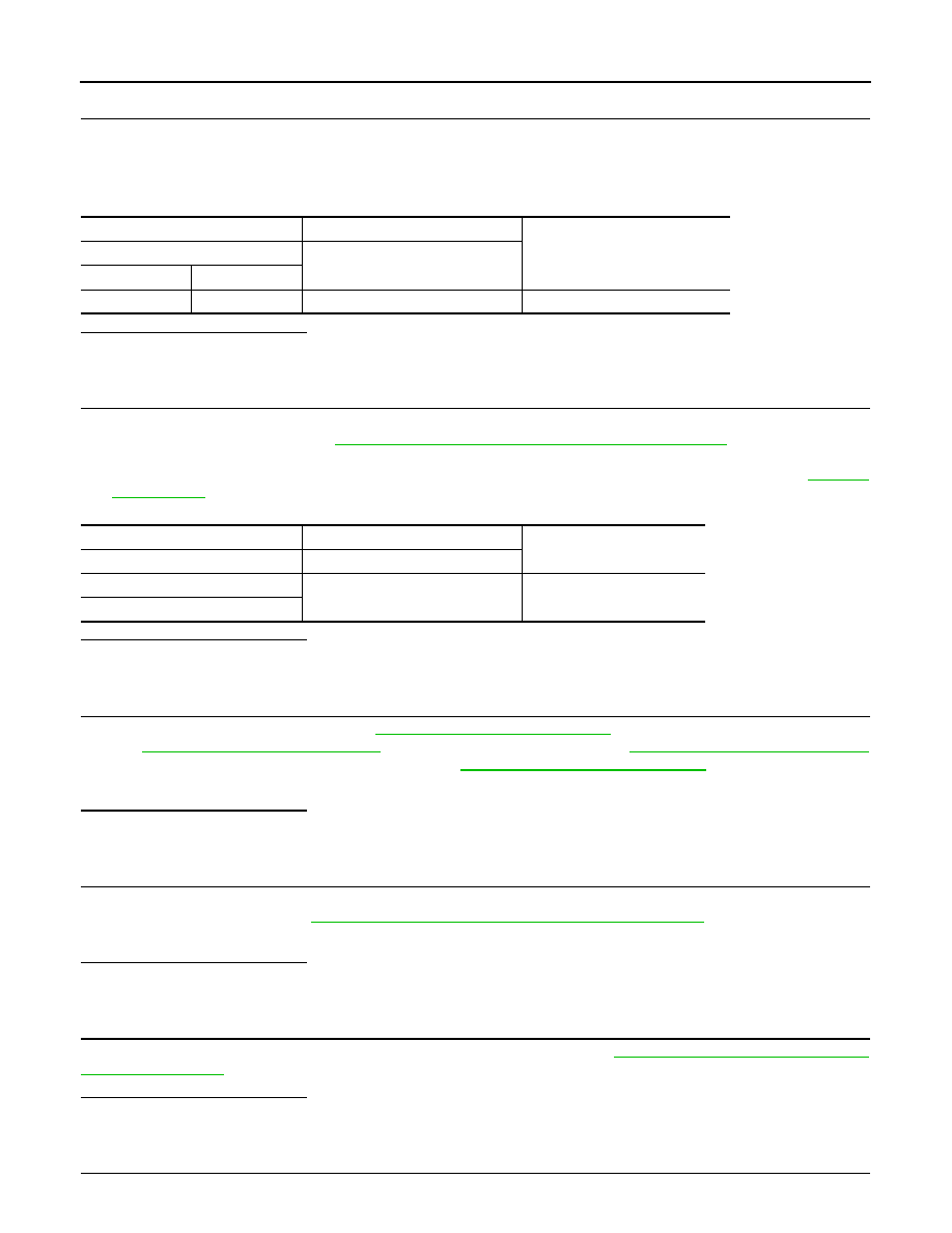
Check voltage between auto amp. harness connector M53 terminal 18 and ground.
Is the inspection result normal?
YES
>> Replace auto amp.
NO
>> Repair harness or connector.
10.
CHECK POWER VOLTAGE OF BLOWER RELAY
1.
Turn ignition switch OFF.
2.
Remove blower relay. Refer to
PG-110, "Fuse, Connector and Terminal Arrangement"
.
3.
Turn ignition switch ON.
4.
Check voltage between blower relay fuse block terminals 1, 3 and body ground. Refer to
for relay terminal assignment.
Is the inspection result normal?
YES
>> GO TO 12.
NO
>> GO TO 11.
11.
CHECK IGNITION SWITCH CIRCUIT
Check ignition switch circuit. Refer to
LOCK),
DLK-355, "Diagnosis Procedure"
(WITH I-KEY & SUPER LOCK),
DLK-597, "Diagnosis Procedure"
(WITHOUT I-KEY, WITHOUT SUPER LOCK) or
DLK-757, "Diagnosis Procedure"
SUPER LOCK).
Is the inspection result normal?
YES
>> Repair harness or connector.
NG
>> Replace malfunctioning parts.
12.
CHECK BLOWER RELAY
1.
Turn ignition switch OFF.
2.
PG-110, "Fuse, Connector and Terminal Arrangement"
3.
Check operation sound of the blower relay after switching ignition switch ON.
Is the inspection result normal?
YES
>> GO TO 13.
NO
>> Replace blower relay.
13.
CHECK FUSE
Check 15A fuse [Nos 15 and 16, located in the fuse block (J/B)]. Refer to
PG-110, "Fuse, Connector and Ter-
.
Is the inspection result normal?
YES
>> Repair harness or connector.
NG
>> Replace fuse.
14.
CHECK CIRCUIT CONTINUITY BETWEEN BLOWER MOTOR AND FAN CONTROL AMP.
(+)
(
−
)
Voltage
Auto amp.
—
Connector
Terminal
M53
18
Ground
Battery voltage
(+)
(
−
)
Voltage
Blower relay
—
1
Ground
Battery voltage
3