Nissan Qashqai (2007-2010). Manual - part 921
 

  Index      Nissan     Nissan Qashqai - service and repair manual 2007 - 2010 year


Search            copyright infringement  


Content   ..  919  920  921  922   ..


Nissan Qashqai (2007-2010). Manual - part 921


HAC-44

< FUNCTION DIAGNOSIS >

[AUTOMATIC AIR CONDITIONER]

BLOWER MOTOR CONTROL SYSTEM

In the most extreme case (very low ambient temperature) the blower starting delay will be 150 seconds as
described above. After this delay, the blower will operate at low speed until the engine coolant temperature
rises above 56

°

C (133

°

F), and then the blower speed will increase to the objective speed.

Start up from usual or HOT SOAK Condition (Automatic mode)
The blower will begin operation momentarily after the AUTO switch is pressed. The blower speed will gradu-
ally rise to the objective speed over a time period of 3 seconds or less (actual time depends on the objective
blower speed).

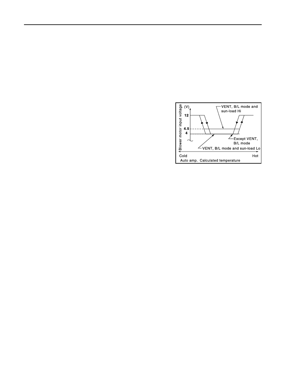
Blower Speed Compensation

Sunload
When the in-vehicle temperature and the set temperature are very close, the blower will be operating at low
speed. The low speed will vary depending on the sunload. During conditions of low or no sunload, the blower
speed is low (approx. 4 V). During high sunload conditions, the auto amp. raise the blower speed (approx. 4.5
V).

Fan Speed Control Specification

JSIIA0312GB

MAGNET CLUTCH CONTROL SYSTEM

HAC-45

< FUNCTION DIAGNOSIS >

[AUTOMATIC AIR CONDITIONER]

C

D

E

F

G

H

J

K

L

M

A

B

HAC

N

O

P

MAGNET CLUTCH CONTROL SYSTEM

Description

INFOID:0000000000954642

SYSTEM DESCRIPTION

Auto amp. controls compressor operation by ambient temperature, intake air temperature and signal from
ECM.

System Operation

Low Temperature Protection Control

Auto amp. will turn compressor ON or OFF as determined by a signal detected by OAT sensor and intake sen-
sor.
When ambient temperature is higher than 

2

°

C (23

°

F), the compres-

sor turns ON. The compressor turns OFF when ambient temperature
is lower than 

5

°

C (28

°

F).

JPIIA0120GB

RHA094GB

HAC-46

< FUNCTION DIAGNOSIS >

[AUTOMATIC AIR CONDITIONER]

PTC HEATER CONTROL SYSTEM

PTC HEATER CONTROL SYSTEM

Description

INFOID:0000000001026642

SYSTEM DESCRIPTION

BCM controls PTC (Positive Temperature Coefficient) heater correspond to fan ON signal, ambient tempera-
ture, engine coolant temperature, engine speed, engine status, electrical power cut freeze signal and battery
voltage.
BCM sends PTC ON signal to IPDM E/R, via CAN communication.
BCM judges whether PTC can be turned ON, based on each sensor status (ambient temperature, engine
speed, engine coolant temperature, etc.). If it judges PTC can be turned ON, it send PTC heater relay ON sig-
nal to IPDM E/R via CAN communication.

System Operation

JSIIA0292GB

MODE DOOR MOTOR

HAC-47

< COMPONENT DIAGNOSIS >

[AUTOMATIC AIR CONDITIONER]

C

D

E

F

G

H

J

K

L

M

A

B

HAC

N

O

P

COMPONENT DIAGNOSIS

MODE DOOR MOTOR

Description

INFOID:0000000000954643

COMPONENT DESCRIPTION

Mode Door Motor

The mode door motor (1) are attached to the A/C unit assembly. It
rotates so that air is discharged from the outlet set by the auto amp.
Motor rotation is conveyed to a link which activates the mode door.

Component Function Check

INFOID:0000000000954644

1.

CONFIRM SYMPTOM BY PERFORMING THE FOLLOWING OPERATIONAL CHECK

1.

Press MODE switches and DEF switch.

2.

Each position indicator should illuminate.

3.

Confirm that discharge air comes out according to the air distribution table at below. Refer to 

HAC-15,

"System Description"

.

NOTE:
Confirm that the magnet clutch is engaged (Sound or visual inspection) and intake door position is at FRE
when DEF 

 or D/F 

 is selected.

Is the inspection result normal?

YES

>> END.

NO

>> Go to diagnosis procedure. Refer to 

HAC-47, "Diagnosis Procedure"

.

Diagnosis Procedure

INFOID:0000000000954645

1.

PERFORM SELF-DIAGNOSIS STEP-2

Perform self-diagnosis STEP-2. Refer to 

HAC-27, "Diagnosis Description"

, see No. 1 to 3.

Does code No. 20 appear on the display?

YES

>> GO TO 2.

NO

>> Go to appropriate malfunctioning sensor circuit. Refer to 

HAC-27, "Diagnosis Description"

, see

No. 11.

2.

PERFORM SELF-DIAGNOSIS STEP-3

Perform self-diagnosis STEP-3. Refer to 

HAC-27, "Diagnosis Description"

, see No. 1 to 4.

Does code No. 30 appear on the display?

YES

>> GO TO 8.

NO-1

>> Code No. 33, 34, 35 or 36 appear on the display: GO TO 3.

NO-2

>> Code No. 37, 38 or 39 appear on the display: Go to Intake Door Motor Circuit. Refer to 

HAC-59,

"Diagnosis Procedure"

.

NO-3

>> Code No. 31 or 32 appear on the display: Go to High-level Ventilator Door Motor Circuit. Refer to

HAC-50, "Diagnosis Procedure"

.

3.

CHECK POWER SUPPLY FOR AUTO AMP.

1.

Turn ignition switch ON.

2.

Check voltage between auto amp. harness connector M53 terminal 20 and ground.

:

Vehicle front

JPIIA0023ZZ


Content   ..  919  920  921  922   ..