Nissan Qashqai (2007-2010). Manual - part 868
 

  Index      Nissan     Nissan Qashqai - service and repair manual 2007 - 2010 year


Search            copyright infringement  


Content   ..  866  867  868  869   ..


Nissan Qashqai (2007-2010). Manual - part 868


HA-42

< ON-VEHICLE REPAIR >

[AUTOMATIC AIR CONDITIONER (HR/MR)]

LOW-PRESSURE FLEXIBLE HOSE AND PIPE 2

3.

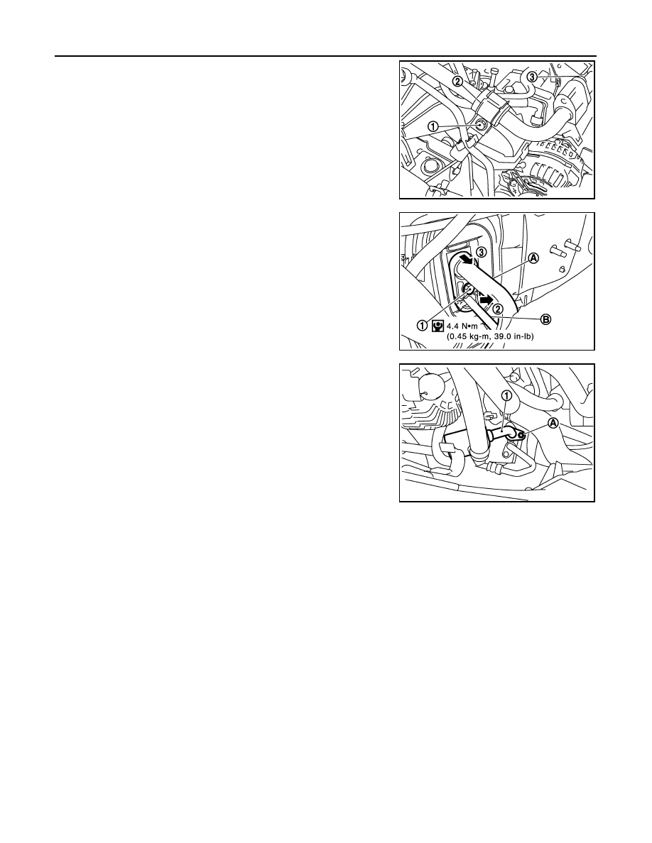
Remove mounting bolt (1) and clamp (2), from low pressure pipe
bracket support.

4.

Remove low and high-pressure maintaining clip, from both
pipes, then remove fixing bolt (3).

5.

Remove engine room insulator fixing clip from cowl top.

6.

Pull engine room insulator, then remove pipes bracket fixing bolt
(1), from expansion valve, and release pipes fixing bracket, as
shown in order (1) to (3), from high pressure pipe (B), to remove
low pressure flexible hose and pipe2 (A) from expansion valve.

CAUTION:

Cap or wrap the joint of the low pressure flexible hose and
pipe 2, and expansion valve exit with suitable material such
as vinyl tape to avoid the entry of air.

7.

Remove low pressure flexible hose fixing nut (A), from air condi-
tioner compressor, and remove low pressure flexible hose (1).

CAUTION:

Cap or wrap the joint of low-pressure flexible hose with
suitable material such as vinyl tape to avoid the entry of air.

INSTALLATION

Installation is basically the reverse order of removal.

CAUTION:

• Replace O-rings of low-pressure flexible hose and low-pressure pipe 2 with new ones, and then

apply compressor oil to it when installing it.

• Female-side piping connection is thin and easy to deform. Slowly insert the male-side piping

straight in axial direction.

• Insert piping securely until a click is heard.
• After piping connection is completed, pull male-side piping by hand to make sure that connection

does not come loose.

• When recharging refrigerant, check for leaks.

E1KIA0040ZZ

E1IIA0011GB

JMIIA0001ZZ

HIGH-PRESSURE FLEXIBLE HOSE

HA-43

< ON-VEHICLE REPAIR >

[AUTOMATIC AIR CONDITIONER (HR/MR)]

C

D

E

F

G

H

J

K

L

M

A

B

HA

N

O

P

HIGH-PRESSURE FLEXIBLE HOSE

Exploded View

INFOID:0000000001093788

Refer to 

HA-18, "Refrigerant Connection"

.

Removal and Installation

INFOID:0000000001093789

REMOVAL

1.

Use a refrigerant collecting equipment (for HFC-134a) to discharge the refrigerant.

2.

Remove engine cover ornament. Refer to 

EM-146, "Exploded View"

 (MR engine models).

3.

Remove air intake hose (RH) and air duct (LH). Refer to 

EM-27, "Exploded View"

 (HR engine models) or

EM-144, "Exploded View"

 (MR engine models).

4.

Remove front grille. Refer to 

EXT-17, "Removal and Installation"

.

1.

Heater & blower unit assembly

2.

Heater & cooling unit assembly

3.

Evaporator

4.

O-ring

5.

Low pressure pipe 1 and high pres-
sure pipe 2 assembly

6.

Expansion valve

7.

Heater sealing

8.

Low pressure flexible hose and pipe 
2

9.

Low pressure pipe 2 fixing clamp as-
sembly

10. High pressure flexible hose

11.

Compressor

12. Low pressure flexible hose

13. Low & high pipe bracket support

14. High pressure pipe 1

15. Condenser assembly

16. Liquid tank fixing bracket

17. Refrigerant pressure sensor

18. Liquid tank

E1KIA0037GB

HA-44

< ON-VEHICLE REPAIR >

[AUTOMATIC AIR CONDITIONER (HR/MR)]

HIGH-PRESSURE FLEXIBLE HOSE

5.

Remove high pressure flexible hose fixing bolt (1) from con-
denser (3), then pull high pressure flexible hose (2) to remove it
from condenser.

CAUTION:

Cap or wrap the joint of high-pressure flexible hose and
condenser assembly with suitable material such as vinyl
tape to avoid the entry of air.

6.

Remove high pressure flexible hose fixing bolt (A) from com-
pressor, then pull high pressure flexible hose (1) to remove it
from compressor. Remove high pressure flexible hose.

CAUTION:

Cap or wrap the joint of compressor and high-pressure flex-
ible hose with suitable material such as vinyl tape to avoid
the entry of air.

INSTALLATION

Installation is basically the reverse order of removal.

CAUTION:

• Replace O-rings of high-pressure flexible hose with new ones, and then apply compressor oil to it

when installing it.

• Female-side piping connection is thin and easy to deform. Slowly insert the male-side piping

straight in axial direction.

• Insert piping securely until a click is heard.
• After piping connection is completed, pull male-side piping by hand to make sure that connection

does not come loose.

• When recharging refrigerant, check for leaks.

E1KIA0043GB

High pressure fixing bolt to condenser

: 4.4 N·m (0.45 kg-m, 39 in-lb)

High pressure fixing bolt to compressor

: 4.4 N·m (0.45 kg-m, 39 in-lb)

JMIIA0001ZZ

HIGH-PRESSURE PIPE 1 (ENGINE COMPARTMENT)

HA-45

< ON-VEHICLE REPAIR >

[AUTOMATIC AIR CONDITIONER (HR/MR)]

C

D

E

F

G

H

J

K

L

M

A

B

HA

N

O

P

HIGH-PRESSURE PIPE 1 (ENGINE COMPARTMENT)

Exploded View

INFOID:0000000001093790

Refer to 

HA-18, "Refrigerant Connection"

.

Removal and Installation

INFOID:0000000001093791

REMOVAL

1.

Use a refrigerant collecting equipment (for HFC-134a) to discharge the refrigerant.

2.

Remove intake hose (RH) and air duct (LH). Refer to 

EM-35, "Removal and Installation"

EM-155,

"Removal and Installation"

 (MR engine).

3.

Pull engine room insulator, then remove pipes bracket fixing bolt
(1), from expansion valve, then release pipe fixing bracket as
shown in order (1) to (3) from high pressure pipe 1 (B), to dis-
connect it from expansion valve.

CAUTION:

Cap or wrap the joint of the high pressure pipe 1, and
expansion valve in, with suitable material such as vinyl tape
to avoid the entry of air.

1.

Heater & blower unit assembly

2.

Heater & cooling unit assembly

3.

Evaporator

4.

O-ring

5.

Low pressure pipe 1 and high pres-
sure pipe 2 assembly

6.

Expansion valve

7.

Heater sealing

8.

Low pressure flexible hose and pipe 
2

9.

Low pressure pipe 2 fixing clamp as-
sembly

10. High pressure flexible hose

11.

Compressor

12. Low pressure flexible hose

13. Low & high pipe bracket support

14. High pressure pipe 1

15. Condenser assembly

16. Liquid tank fixing bracket

17. Refrigerant pressure sensor

18. Liquid tank

E1KIA0037GB

E1IIA0011GB


Content   ..  866  867  868  869   ..