Nissan Qashqai (2007-2010). Manual - part 861
 

  Index      Nissan     Nissan Qashqai - service and repair manual 2007 - 2010 year


Search            copyright infringement  


Content   ..  859  860  861  862   ..


Nissan Qashqai (2007-2010). Manual - part 861


HA-14

< SYMPTOM DIAGNOSIS >

[AUTOMATIC AIR CONDITIONER (HR/MR)]

REFRIGERATION SYSTEM SYMPTOMS

LOW-PRESSURE SIDE SOMETIMES BECOMES NEGATIVE

LOW-PRESSURE SIDE SOMETIMES BECOMES NEGATIVE : Symptom Table

INFOID:0000000001093760

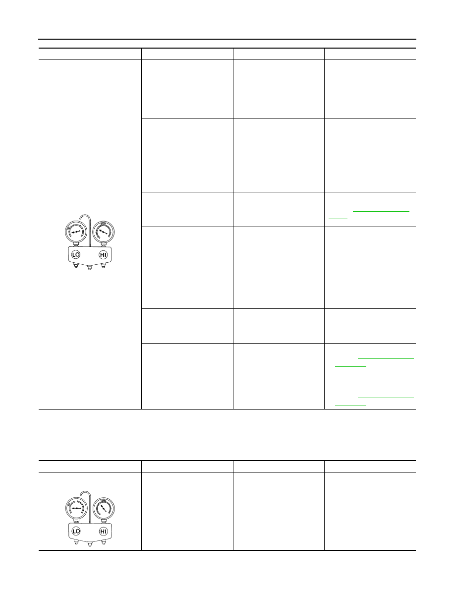
LOW-PRESSURE SIDE BECOMES NEGATIVE

Gauge indication

Refrigerant cycle

Probable cause

Corrective action

Both high- and low-pressure sides 
are too low.

• There is a big temperature 

difference between liquid 
tank outlet and inlet. Outlet 
temperature is extremely 
low.

• Liquid tank inlet and expan-

sion valve are frosted.

Liquid tank inside is slightly 
clogged.

• Replace liquid tank.
• Check lubricant for contami-

nation.

• Temperature of expansion 

valve inlet is extremely low 
as compared with areas 
near liquid tank.

• Expansion valve inlet is 

frosted.

• Temperature difference oc-

curs somewhere in high-
pressure side.

High-pressure pipe located be-
tween liquid tank and expan-
sion valve is clogged.

• Check and repair malfunc-

tioning parts.

• Check lubricant for contami-

nation.

Expansion valve and liquid 
tank are warm or slightly cool 
when touched.

Low refrigerant charge.

Leaking fittings or compo-
nents.

Check refrigerant for leaks. 
Refer to 

HA-30, "Refrigerant 

Leaks"

.

There is a big temperature dif-
ference between expansion 
valve inlet and outlet while the 
valve itself is frosted.

Expansion valve closes a little 
compared with the specifica-
tion.

1.

Improper expansion 
valve adjustment.

2.

Malfunctioning expansion 
valve.

3.

Outlet and inlet may be 
clogged.

• Remove foreign particles by 

using compressed air.

• Replace expansion valve.
• Check lubricant for contami-

nation.

An area of the low-pressure 
pipe is colder than areas near 
the evaporator outlet.

Low-pressure pipe is clogged 
or crushed.

• Check and repair malfunc-

tioning parts.

• Check lubricant for contami-

nation.

Air flow volume is not enough 
or is too low.

Evaporator is frozen.

• Check intake sensor circuit.

Refer to 

HAC-59, "Diagnosis 

Procedure"

.

• Replace compressor.
• Repair evaporator fins.
• Replace evaporator.
• Refer  to 

HAC-62, "Diagnosis 

Procedure"

.

AC353A

Gauge indication

Refrigerant cycle

Probable cause

Corrective action

Low-pressure side sometimes be-
comes negative.

• Air conditioning system does 

not function and does not cy-
clically cool the compart-
ment air.

• The system constantly func-

tions for a certain period of 
time after compressor is 
stopped and restarted.

Refrigerant does not discharge 
cyclically.

Moisture is frozen at expan-
sion valve outlet and inlet.

Water is mixed with refrigerant.

• Drain water from refrigerant 

or replace refrigerant.

• Replace liquid tank.

AC354A

REFRIGERATION SYSTEM SYMPTOMS

HA-15

< SYMPTOM DIAGNOSIS >

[AUTOMATIC AIR CONDITIONER (HR/MR)]

C

D

E

F

G

H

J

K

L

M

A

B

HA

N

O

P

LOW-PRESSURE SIDE BECOMES NEGATIVE : Symptom Table

INFOID:0000000001093761

Gauge indication

Refrigerant cycle

Probable cause

Corrective action

Low-pressure side becomes nega-
tive.

Liquid tank or front/rear side of 
expansion valve’s pipe is frost-
ed or wet with dew.

High-pressure side is closed 
and refrigerant does not flow.

Expansion valve or liquid tank 
is frosted.

Leave the system at rest until 
no frost is present. Start it 
again to check whether or not 
the malfunction is caused by 
water or foreign particles.
• If water is the cause, initially 

cooling is okay. Then the wa-
ter freezes causing a block-
age. Drain water from 
refrigerant or replace refrig-
erant.

• If due to foreign particles, re-

move expansion valve and 
remove the particles with dry 
and compressed air (not 
shop air).

• If either of the above meth-

ods cannot correct the mal-
function, replace expansion 
valve.

• Replace liquid tank.
• Check lubricant for contami-

nation.

AC362A

HA-16

< PRECAUTION >

[AUTOMATIC AIR CONDITIONER (HR/MR)]

PRECAUTIONS

PRECAUTION

PRECAUTIONS

Precaution for Supplemental Restraint System (SRS) "AIR BAG" and "SEAT BELT 
PRE-TENSIONER"

INFOID:0000000001115386

The Supplemental Restraint System such as “AIR BAG” and “SEAT BELT PRE-TENSIONER”, used along
with a front seat belt, helps to reduce the risk or severity of injury to the driver and front passenger for certain
types of collision. This system includes seat belt switch inputs and dual stage front air bag modules. The SRS
system uses the seat belt switches to determine the front air bag deployment, and may only deploy one front
air bag, depending on the severity of a collision and whether the front occupants are belted or unbelted.
Information necessary to service the system safely is included in the SRC and SB section of this Service Man-
ual.

WARNING:

• To avoid rendering the SRS inoperative, which could increase the risk of personal injury or death in

the event of a collision which would result in air bag inflation, all maintenance must be performed by
an authorized NISSAN/INFINITI dealer.

• Improper maintenance, including incorrect removal and installation of the SRS, can lead to personal

injury caused by unintentional activation of the system. For removal of Spiral Cable and Air Bag
Module, see the SRC section.

• Do not use electrical test equipment on any circuit related to the SRS unless instructed to in this

Service Manual. SRS wiring harnesses can be identified by yellow and/or orange harnesses or har-
ness connectors.

Precaution Necessary for Steering Wheel Rotation After Battery Disconnect

INFOID:0000000001115391

NOTE:
• This Procedure is applied only to models with Intelligent Key system and NATS (NISSAN ANTI-THEFT SYS-

TEM).

• Remove and install all control units after disconnecting both battery cables with the ignition knob in the

LOCK

 position.

• Always use CONSULT-III to perform self-diagnosis as a part of each function inspection after finishing work.

If DTC is detected, perform trouble diagnosis according to self-diagnostic results.

For models equipped with the Intelligent Key system and NATS, an electrically controlled steering lock mech-
anism is adopted on the key cylinder.
For this reason, if the battery is disconnected or if the battery is discharged, the steering wheel will lock and
steering wheel rotation will become impossible.
If steering wheel rotation is required when battery power is interrupted, follow the procedure below before
starting the repair operation.

OPERATION PROCEDURE

1.

Connect both battery cables.
NOTE:
Supply power using jumper cables if battery is discharged.

2.

Use the Intelligent Key or mechanical key to turn the ignition switch to the 

ACC

 position. At this time, the

steering lock will be released.

3.

Disconnect both battery cables. The steering lock will remain released and the steering wheel can be
rotated.

4.

Perform the necessary repair operation.

5.

When the repair work is completed, return the ignition switch to the 

LOCK

 position before connecting

the battery cables. (At this time, the steering lock mechanism will engage.)

6.

Perform a self-diagnosis check of all control units using CONSULT-III. 

Precaution for Procedure without Cowl Top Cover

INFOID:0000000001115394

PRECAUTIONS

HA-17

< PRECAUTION >

[AUTOMATIC AIR CONDITIONER (HR/MR)]

C

D

E

F

G

H

J

K

L

M

A

B

HA

N

O

P

When performing the procedure after removing cowl top cover, cover
the lower end of windshield with urethane, etc.

Precautions For Xenon Headlamp Service

INFOID:0000000001115398

WARNING:

Comply with the following warnings to prevent any serious accident.
• Disconnect the battery cable (negative terminal) or the power supply fuse before installing, remov-

ing, or touching the xenon headlamp (bulb included). The xenon headlamp contains high-voltage
generated parts.

• Never work with wet hands.
• Check the xenon headlamp ON-OFF status after assembling it to the vehicle. Never turn the xenon

headlamp ON in other conditions. Connect the power supply to the vehicle-side connector.
(Turning it ON outside the lamp case may cause fire or visual impairments.)

• Never touch the bulb glass immediately after turning it OFF. It is extremely hot. 

CAUTION:

Comply with the following cautions to prevent any error and malfunction.
• Install the xenon bulb securely. (Insufficient bulb socket installation may melt the bulb, the connec-

tor, the housing, etc. by high-voltage leakage or corona discharge.)

• Never perform HID circuit inspection with a tester.
• Never touch the xenon bulb glass with hands. Never put oil and grease on it.
• Dispose of the used xenon bulb after packing it in thick vinyl without breaking it. 
• Never wipe out dirt and contamination with organic solvent (thinner, gasoline, etc.).

Working with HFC-134a (R-134a)

INFOID:0000000001093766

CAUTION:

• CFC-12 (R-12) refrigerant and HFC-134a (R-134a) refrigerant are not compatible. These refrigerants

must never be mixed, even in the smallest amounts. If the refrigerants are mixed and compressor
malfunction is likely occur.

• Use only specified lubricant for the HFC-134a (R-134a) A/C system and HFC-134a (R-134a) compo-

nents. If lubricant other than that specified is used, compressor malfunction is likely to occur.

• The specified HFC-134a (R-134a) lubricant rapidly absorbs moisture from the atmosphere. The fol-

lowing handling precautions must be observed:

- When removing refrigerant components from a vehicle, immediately cap (seal) the component to

minimize the entry of moisture from the atmosphere.

- When installing refrigerant components to a vehicle, never remove the caps (unseal) until just before

connecting the components. Connect all refrigerant loop components as quickly as possible to min-
imize the entry of moisture into system.

- Only use the specified lubricant from a sealed container. Immediately reseal containers of lubricant.

Without proper sealing, lubricant will become moisture saturated and should not be used.

- Never allow lubricant (Nissan A/C System Oil Type S) to come in contact with styrene foam parts.

Damage may result.

General Refrigerant Precaution

INFOID:0000000001093767

WARNING:

• Avoid breathing A/C refrigerant and lubricant vapor or mist. Exposure may irritate eyes, nose and

throat. Use only approved recovery/recycling equipment to discharge HFC-134a (R-134a) refrigerant.
If accidental system discharge occurs, ventilate work area before resuming service. Additional
health and safety information may be obtained from refrigerant and lubricant manufacturers.

PIIB3706J


Content   ..  859  860  861  862   ..