Nissan Qashqai (2007-2010). Manual - part 627
DRIVE PINION
DLN-81
< DISASSEMBLY AND ASSEMBLY >
[TRANSFER: TY30A]
C
E
F
G
H
I
J
K
L
M
A
B
DLN
N
O
P
CAUTION:
Check that the drive pinion bearing preload is within the standard.
2.
Assemble the ring gear shaft assembly to the transfer case.
3.
Install adapter case. Refer to
4.
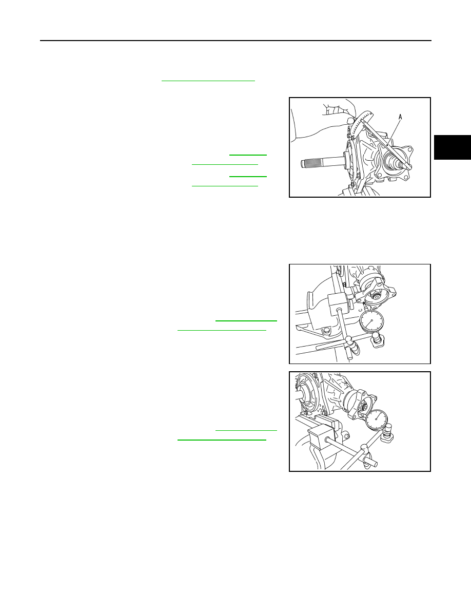
Rotate the companion flange at least 20 times to check for smooth operation of the bearing.
5.
Measure the total preload with a preload gauge (A) (SST:
ST3127S000).
CAUTION:
• Each rotational part should rotate smoothly with the spec-
ified gear oil.
• Disassemble the transfer assembly to check and adjust each part if outside the standard. Mea-
sure it with the adapter case oil seals removed when measuring total preload after disassembly.
Then install adapter case oil seals.
COMPANION FLANGE RUNOUT
1.
Fit a dial indicator onto the companion flange face (inner side of
the propeller shaft bolt holes).
2.
Rotate the companion flange to check for runout.
3.
Fit a test indicator to the inner side of the companion flange
(socket diameter).
4.
Rotate the companion flange to check for runout.
5.
Follow the procedure below to adjust if runout value is outside
the repair limit.
CAUTION:
Replace collapsible spacer to check and adjust each part
when companion flange is adjusted or replaced.
a.
Check for runout while changing the phase between companion flange and drive pinion in 90
°
steps. Then
search for the minimum point.
b.
Replace companion flange if runout value is still outside the limit after the phase has been changed.
c.
Adjust assembly status of the drive pinion bearings and drive pinion, or replace drive pinion bearings if
runout is outside the standard after the companion flange is replaced.
ADJUSTING SHIM SELECTION
Measuring Point
Standard
Total preload
All oil seals are installed
: Refer to
.
Without adapter case oil seal
: Refer to
.
SDIA3073J
Limit
Companion flange runout
: Refer to
.
SDIA3074J
Limit
Companion flange runout
: Refer to
.
SDIA3075J