Nissan Qashqai (2007-2010). Manual - part 533
 

  Index      Nissan     Nissan Qashqai - service and repair manual 2007 - 2010 year


Search            copyright infringement  


Content   ..  531  532  533  534   ..


Nissan Qashqai (2007-2010). Manual - part 533


AIR BREATHER HOSE

TM-67

< ON-VEHICLE REPAIR >

[6MT: RS6F94R]

C

E

F

G

H

I

J

K

L

M

A

B

TM

N

O

P

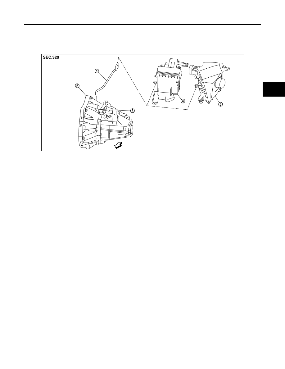
AIR BREATHER HOSE

Exploded View

INFOID:0000000001070333

Removal and Installation

INFOID:0000000001070334

REMOVAL

Refer to the figure for removal procedure.

CAUTION:

When removing air breather hose, be sure to hold two way connector securely.

INSTALLATION

Refer to the figure for installation procedure.
• When installing air breather hose on two way connector, aim paint mark face toward the vehicle front.
• When installing air breather hose on two way connector, push it until it hits transaxle case.
• When installing air breather hose to air cleaner case, make sure that clip are fully inserted.

CAUTION:

Make sure air breather hose is not collapsed or blocked due to folding or bending when installed.

1.

Air breather hose

2.

Transaxle assembly

3.

Two way connector

4.

Air cleaner case (MR20DE)

5.

Air cleaner case (K9K)

: Vehicle front

JPDIC0052ZZ

TM-68

< REMOVAL AND INSTALLATION >

[6MT: RS6F94R]

TRANSAXLE ASSEMBLY

REMOVAL AND INSTALLATION

TRANSAXLE ASSEMBLY

Exploded View

INFOID:0000000001070335

MR20DE

CAUTION:

If transaxle assembly is removed from the vehicle, always replace CSC (Concentric Slave Cylinder). Return CSC insert to orig-
inal position to remove transaxle assembly. Dust on clutch disc sliding parts may damage seal of CSC and may cause clutch
fluid leakage.

K9K

CAUTION:

JPDIC0062GB

1.

Transaxle assembly

: For the bolt mounting positions, refer to “INSTALLATION”.

Refer to 

GI-4, "Components"

 for symbols not described on the above.

JPDIC0121GB

1.

Transaxle assembly

: For the bolt mounting positions, refer to “INSTALLATION”.

Refer to 

GI-4, "Components"

 for symbols not described on the above.

TRANSAXLE ASSEMBLY

TM-69

< REMOVAL AND INSTALLATION >

[6MT: RS6F94R]

C

E

F

G

H

I

J

K

L

M

A

B

TM

N

O

P

If transaxle assembly is removed from the vehicle, always replace CSC (Concentric Slave Cylinder). Return CSC insert to orig-
inal position to remove transaxle assembly. Dust on clutch disc sliding parts may damage seal of CSC and may cause clutch
fluid leakage.

Removal and Installation

INFOID:0000000001070336

CAUTION:

If transaxle assembly is removed from the vehicle, always replace CSC (Concentric Slave Cylinder).
Return CSC insert to original position to remove transaxle assembly. Dust on clutch disc sliding parts
may damage seal of CSC and may cause clutch fluid leakage.

REMOVAL

1.

Disconnect the battery cable from the negative terminal.

2.

Remove air breather hose. Refer to 

TM-67, "Removal and Installation"

.

3.

Remove air cleaner case and air duct (inlet). Refer to 

EM-144, "Removal and Installation"

 (MR20DE) or

EM-265, "Removal and Installation"

 (K9K).

4.

Remove battery. Refer to 

PG-118, "Removal and Installation"

.

5.

Disconnect connectors (A) and then remove bracket (1).

6.

Drain clutch fluid and then remove clutch tube from CSC (Con-
centric Slave Cylinder). Refer to 

CL-14, "Removal and Installa-

tion"

.

CAUTION:

Never depress clutch pedal during removal procedure.

7.

Disconnect position switch harness connector.

8.

Remove crankshaft position sensor (POS). (For K9K) Refer to

EM-280, "Removal and Installation"

.

CAUTION:

• Handle carefully to avoid dropping and shocks.
• Never disassemble.
• Never allow metal powder to adhere to magnetic part at sensor tip.
• Never place sensors in a location where they are exposed to magnetism.

9.

Disconnect ground cable.

10. Remove wire harnesses from transaxle assembly.

11. Disconnect select cable and shift cable from transaxle assembly. Refer to 

TM-63, "Removal and Installa-

tion"

.

12. Remove starter motor. Refer to 

STR-27, "MR20DE MODELS : Removal and Installation"

 (MR20DE) or

STR-20, "K9K MODELS : Removal and Installation"

 (K9K).

13. Remove engine under cover.

14. Drain gear oil. Refer to 

TM-61, "Draining"

.

15. Remove exhaust front tube. Refer to 

EX-10, "Removal and Installation"

 (MR20DE) or 

EX-15, "Removal

and Installation"

 (K9K).

16. Remove front drive shafts. Refer to 

FAX-25, "MR20DE MODELS : Removal and Installation"

 (MR20DE) or

FAX-33, "K9K MODELS : Removal and Installation"

 (K9K).

NOTE:
Insert a suitable plug into differential side oil seal after removing front drive shaft.

17. Remove rear engine mounting brackets and rear torque rod. (For MR20DE) Refer to 

EM-195, "M/T :

Removal and Installation"

.

18. Remove transaxle mounting lower brackets and transaxle torque rod. (For K9K) Refer to 

EM-298,

"Removal and Installation"

.

19. Remove suspension member and suspension member stay. Refer to 

FSU-17, "Removal and Installation"

.

20. Set a suitable jack to transaxle assembly and then set a suitable jack to engine assembly.

CAUTION:

When setting a suitable jack, be careful so that it does not contact with the switch.

21. Remove transaxle assembly mounting bolts.

22. Remove engine mounting through bolt-securing nut. Refer to 

EM-195, "M/T : Removal and Installation"

(MR20DE) or 

EM-298, "Removal and Installation"

 (K9K).

JPDIA0240ZZ

TM-70

< REMOVAL AND INSTALLATION >

[6MT: RS6F94R]

TRANSAXLE ASSEMBLY

23. Remove transaxle assembly from the vehicle.

CAUTION:

• Secure transaxle assembly to a suitable jack while removing it.
• The transaxle assembly must not interfere with the wire harnesses and clutch tube.

24. Remove CSC (Concentric Slave Cylinder). Refer to 

CL-15, "Removal and Installation"

.

CAUTION:

If transaxle assembly is removed from the vehicle, always replace CSC (Concentric Slave Cylin-
der). Return CSC insert to original position to remove transaxle assembly. Dust on clutch disc
sliding parts may damage seal of CSC and may cause clutch fluid leakage.

INSTALLATION

Note the following, and install in the reverse order of removal.
• Tighten transaxle assembly mounting bolts to the specified torque. The figure is the view from the engine.
MR20DE

K9K

CAUTION:

• The transaxle assembly must not interfere with the wire harnesses and clutch tube.
• When installing transaxle assembly, never bring input shaft into contact with clutch cover.
• Refer to 

CL-15, "Removal and Installation"

 for CSC (Concentric Slave Cylinder) installation procedure.

• Refer to 

TM-63, "Removal and Installation"

 for select cable and shift cable installation procedure.

• Bleed the air from the clutch hydraulic system. Refer to 

CL-6, "Air Bleeding Procedure"

.

• After installation, check for oil leakage and oil level. Refer to 

TM-61, "Inspection"

.

: Transaxle to engine

: Engine to transaxle

Bolt symbol

A

B

Quantity

3

6

” mm (in)

60 (2.36)

50 (1.97)

JPDIC0094ZZ

: Transaxle to engine

: Engine to transaxle

Bolt symbol

A

B

C

Quantity

2

2

4

” mm (in)

50 (1.97)

80 (3.15)

65 (2.56)

JPDIC0054ZZ


Content   ..  531  532  533  534   ..