Nissan Qashqai (2007-2010). Manual - part 474
 

  Index      Nissan     Nissan Qashqai - service and repair manual 2007 - 2010 year


Search            copyright infringement  


Content   ..  472  473  474  475   ..


Nissan Qashqai (2007-2010). Manual - part 474


P2610 ENGINE SAFETY STOP

EC-1415

< COMPONENT DIAGNOSIS >

[K9K]

C

D

E

F

G

H

I

J

K

L

M

A

EC

N

P

O

P2610 ENGINE SAFETY STOP

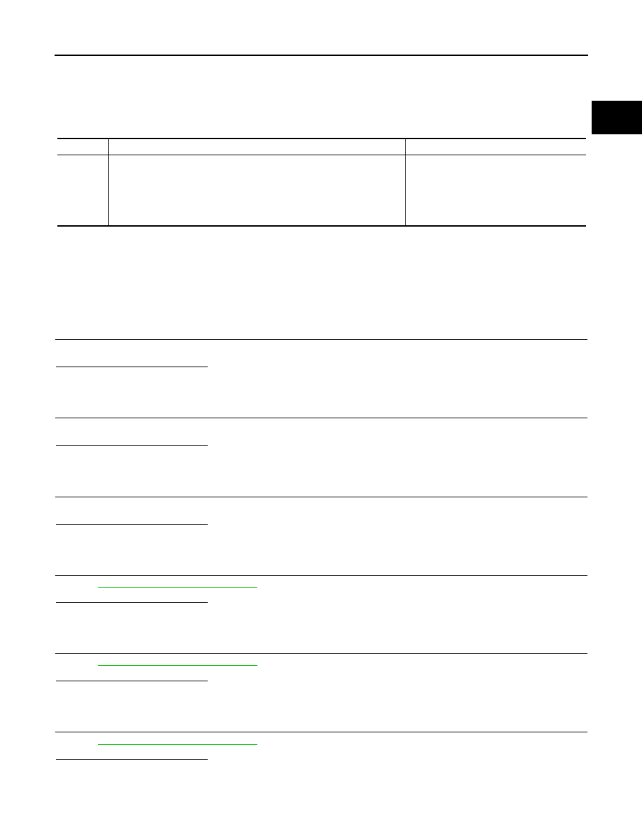
DTC Logic

INFOID:0000000001115116

DTC DETECTION LOGIC

NOTE:
• Priorities when dealing with a number of DTCs:

 If DTC P2610 is displayed with other DTC, first perform the trouble diagnosis for the other DTC.

• Special notes:
- The engine only stops after the ignition is switched off.

Diagnosis Procedure

INFOID:0000000000970938

1.

CHECK INTAKE AIR DUCT

Check that intake air duct is not obstructed.

Is the inspection result normal?

Yes

>> Repair or replace.

No

>> GO TO 2.

2.

CHECK VACUUM PUMP

Check vacuum pump.

Is the inspection result normal?

Yes

>> Repair or replace.

No

>> GO TO 3.

3.

CHECK TURBOCHARGER

Check turbocharger.
Is the inspection result normal?

Yes

>> Repair or replace.

No

>> GO TO 4.

4.

CHECK TURBOCHARGER BOOST CONTROL SOLENOID VALVE

Refer to 

EC-1327, "Diagnosis Procedure"

.

Is the inspection result normal?

YES

>> GO TO 5.

NO

>> Replace turbocharger boost control solenoid valve.

5.

CHECK THROTTLE CONTROL MOTOR

Refer to 

EC-1404, "Diagnosis Procedure"

.

Is the inspection result normal?

YES

>> GO TO 6.

NO

>> Replace turbocharger boost sensor.

6.

CHECK FUEL INJECTOR

Refer to 

EC-1353, "Diagnosis Procedure"

.

Is the inspection result normal?

YES

>> GO TO 7.

NO

>> Replace fuel injector.

DTC No.

Trouble diagnosis name

Possible cause

P2610

ENGINE SAFETY STOP
• 1.DEF: Electric
• 2.DEF: Hydraulic

• Harness or connectors

(Fuel injector circuit is shorted)

• Turbocharger
• Fuel injector
• Intake air leas
• Electric throttle control actuator

EC-1416

< COMPONENT DIAGNOSIS >

[K9K]

P2610 ENGINE SAFETY STOP

7.

CHECK INTERMITTENT INCIDENT

Refer to 

GI-39, "Intermittent Incident"

.

>> INSPECTION END

ASCD INDICATOR

EC-1417

< COMPONENT DIAGNOSIS >

[K9K]

C

D

E

F

G

H

I

J

K

L

M

A

EC

N

P

O

ASCD INDICATOR

Description

INFOID:0000000001102019

ASCD indicator lamp illuminates to indicate ASCD operation status. Lamp has two indicators, CRUISE and
SET, and is integrated in combination meter.
CRUISE lamp illuminates when MAIN switch on ASCD steering switch is turned ON to indicated that ASCD
system is ready for operation.
SET lamp illuminates when following conditions are met. 
• CRUISE lamp is illuminated.
• SET/COAST switch on ASCD steering switch is turned ON while vehicle speed is within the range of ASCD

setting.

SET lamp remains lit during ASCD control.

Component Function Check

INFOID:0000000001102020

1.

ASCD INDICATOR FUNCTION

Check ASCD indicator under the following conditions.

Is the inspection result normal?

YES

>> INSPECTION END

NO

>> Go to 

EC-1421, "Diagnosis Procedure"

.

Diagnosis Procedure

INFOID:0000000001102021

1.

CHECK CAN COMMUNICATION LINE

Refer to 

LAN-59, "CAN Communication Signal Chart"

.

OK or NG

OK

>> GO TO 2.

NG

>> Repair or replace.

2.

CHECK COMBINATION METER OPERATION

Refer to 

MWI-23, "CONSULT-III Function (METER/M&A)"

.

Is the inspection result normal?

YES

>> GO TO 3.

NO

>> Check combination meter circuit. Refer to 

MWI-4, "METER SYSTEM : System Diagram"

.

3.

CHECK INTERMITTENT INCIDENT

Refer to 

GI-39, "Intermittent Incident"

.

>> INSPECTION END

CONDITION

INDICATOR

• Ignition switch: ON

• MAIN switch: Pressed at the 

1st time 

at the 2nd time

Illuminated 

 Not illuminated

• MAIN switch: ON
• When vehicle speed: Between 40 km/h (25 

MPH) and 144 km/h (89 MPH)

• ASCD: Operating

Illuminated

• ASCD: Not operating

Not illuminated

EC-1418

< COMPONENT DIAGNOSIS >

[K9K]

COOLING FAN

COOLING FAN

Description

INFOID:0000000001102014

Cooling fan operates at each speed when the current flows in the cooling fan motor as follows.
Refer to 

EC-1309, "System Description"

 for cooling fan operation.

Component Function Check

INFOID:0000000001102015

1.

CHECK COOLING FAN LOW SPEED FUNCTION

1.

Start engine and let it idle.

2.

Turn air conditioner switch and blower fan switch ON.

3.

Make sure that cooling fan operates at low speed.

Is the inspection result normal?

YES

>> GO TO 2.

NO

>> Refer to 

EC-1422, "Diagnosis Procedure"

.

2.

CHECK COOLING FAN HIGH SPEED FUNCTION

1.

Turn ignition switch OFF.

2.

Turn air conditioner switch and blower fan switch OFF.

3.

Disconnect engine coolant temperature sensor harness connector.

4.

Connect 150

 resistor to engine coolant temperature sensor harness connector.

5.

Restart engine and make sure that cooling fan operates at higher speed than low speed.

Is the inspection result normal?

YES

>> INSPECTION END

NO

>> Refer to 

EC-1422, "Diagnosis Procedure"

.

Diagnosis Procedure

INFOID:0000000001102016

1.

CHECK CAN COMMUNICATION LINE

Refer to 

EC-1321, "Component Inspection"

.

Is the inspection result normal?

YES

>> GO TO 2.

NO

>> Repair or replace

2.

CHECK COOLING FAN RELAY POWER SUPPLY CIRCUIT

1.

Turn ignition switch OFF.

2.

Disconnect cooling fan relay-3 harness connector.

3.

Check the voltage between cooling fan relay-3 harness connectors and ground.

Is the inspection result normal?

YES

>> GO TO 4.

NO

>> GO TO 3.

3.

DETECT MALFUNCTIONING PART

Check the following.
• 50A fusible link (letter M)
• Harness for open or short between cooling fan motor-3 and battery 

>> Repair or replace malfunctioning part.

4.

CHECK COOLING FAN CIRCUIT FOR OPEN AND SHORT

Cooling fan motor-1

Ground

Voltage

Connector

Terminal

E59

1

Ground

Battery voltage

3


Content   ..  472  473  474  475   ..