Nissan Qashqai (2007-2010). Manual - part 471
 

  Index      Nissan     Nissan Qashqai - service and repair manual 2007 - 2010 year


Search            copyright infringement  


Content   ..  469  470  471  472   ..


Nissan Qashqai (2007-2010). Manual - part 471


P2120 APP SENSOR

EC-1403

< COMPONENT DIAGNOSIS >

[K9K]

C

D

E

F

G

H

I

J

K

L

M

A

EC

N

P

O

P2120 APP SENSOR

Description

INFOID:0000000001098978

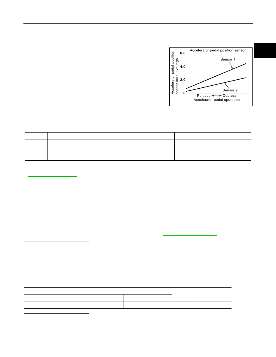
The accelerator pedal position sensor is installed on the upper end
of the accelerator pedal assembly. The sensors detect the accelera-
tor pedal position and sends a signal to the ECM. The ECM uses the
signal to determine the amount of fuel to be injected.

DTC Logic

INFOID:0000000001115105

DTC DETECTION LOGIC

NOTE:
• If DTC P2120 is displayed with DTC P0641, first perform trouble diagnosis for DTC P0641. Refer to

EC-1393, "DTC Logic"

.

• Conditions for applying the diagnostic procedure to the stored DTCs: 
- The DTC is declared present after a series of full load-no load accelerator pedal actions have been carried

out (engine stopped, ignition on).

• If the DTC is present:
Malfunction indicator (Red) lights up.

Diagnosis Procedure

INFOID:0000000000970745

1.

CHECK GROUND CONNECTIONS

1.

Turn ignition switch OFF.

2.

 Check ground connection E17. Refer to Ground inspection in 

GI-41, "Circuit Inspection"

.

Is the inspection result normal?

YES

>> GO TO 2.

NO

>> Repair or replace ground connection.

2.

CHECK ACCELERATOR PEDAL POSITION SENSOR POWER SUPPLY CIRCUIT

1.

Disconnect accelerator pedal position sensor harness connector.

2.

Turn ignition switch ON.

3.

Check the voltage between accelerator pedal position sensor connector and ground.

Is the inspection result normal?

YES

>> GO TO 3.

NO

>> Repair open circuit or short to ground or short to power in harness or connectors.

3.

CHECK ACCELERATOR PEDAL POSITION SENSOR GROUND CIRCUIT FOR OPEN AND SHORT

1.

Turn ignition switch OFF.

PBIB1741E

DTC No.

Trouble diagnosis name

Possible cause

P2120

ACCELERATOR PEDAL POSITION SENSOR 2 CIRCUIT
• CC.1: Short circuit to +12V
• CO.0: Open circuit or short circuit to ground

• Harness or connectors

(APP sensor 2 circuit is open or shorted.)

• Accelerator pedal position sensor 

(APP sensor 2)

Accelerator pedal position sensor

Ground

Voltage

Sensor

Connector

Terminal

2

E110

5

Ground

Approx. 5V

EC-1404

< COMPONENT DIAGNOSIS >

[K9K]

P2120 APP SENSOR

2.

Disconnect accelerator pedal position sensor.

3.

Check the continuity between accelerator pedal position sensor harness connector and ECM harness
connector.

4.

Also check harness for short to ground and short to power. 

Is the inspection result normal?

YES

>> GO TO 4.

NO

>> Repair open circuit or short to ground or short to power in harness or connectors.

4.

CHECK ACCELERATOR PEDAL POSITION SENSOR INPUT SIGNAL CIRCUIT FOR OPEN AND SHORT

1.

Check the continuity between accelerator pedal position sensor harness connector and ECM harness
connector.

2.

Also check harness for short to ground and short to power. 

Is the inspection result normal?

YES

>> GO TO 5.

NO

>> Repair open circuit or short to ground or short to power in harness or connectors.

5.

CHECK ACCELERATOR PEDAL POSITION SENSOR 

Refer to 

EC-1359, "Component Inspection"

.

Is the inspection result normal?

YES

>> GO TO 6.

NO

>> Replace accelerator pedal position sensor.

6.

CHECK INTERMITTENT INCIDENT

Refer to 

GI-39, "Intermittent Incident"

.

>> INSPECTION END

Component Inspection

INFOID:0000000001098962

1.

CHECK ACCELERATOR PEDAL POSITION SENSOR

1.

Turn ignition switch OFF.

2.

Disconnect accelerator pedal position sensor harness connector.

3.

Check resistance between accelerator pedal position sensor as follows.

Is the inspection result normal?

YES

>> INSPECTION END

NO

>> Replace accelerator pedal position sensor.

Accelerator pedal position sensor

ECM

Continuity

Sensor

Connector

Terminal

Connector

Terminal

2

E110

1

E60

120

Existed

Accelerator pedal position sensor

ECM

Continuity

Sensor

Connector

Terminal

Connector

Terminal

2

E110

6

E60

119

Existed

Sensor

Terminals

Resistance

1

2 and 4

1.7 

±

 0.9 K


2

1 and 5

2.85 

±

 2.05 K

P2226 BARO SENSOR

EC-1405

< COMPONENT DIAGNOSIS >

[K9K]

C

D

E

F

G

H

I

J

K

L

M

A

EC

N

P

O

P2226 BARO SENSOR

Description

INFOID:0000000000970747

The barometric pressure sensor is built into ECM. The sensor
detects ambient barometric pressure and sends the voltage signal to
the microcomputer.

DTC Logic

INFOID:0000000001115106

DTC DETECTION LOGIC

NOTE:
• Conditions for applying the diagnostic procedure to the stored DTCs:

The DTC is declared present after the ignition has been switched on for at least 10 seconds.

• Special note:

The barometric pressure sensor is integrated into the ECM, and cannot be separated.

Diagnosis Procedure

INFOID:0000000000970749

1.

REPLACE ECM

1.

Perform 

EC-1273, "ADDITIONAL SERVICE WHEN REPLACING CONTROL UNIT : Special Repair

Requirement"

.

2.

Perform 

EC-1274, "EGR VOLUME CONTROL VALVE CLOSED POSITION LEARNING : Special Repair

Requirement"

.

>> INSPECTION END

MBIB1517E

DTC No.

Trouble diagnosis name

Possible cause

P2226

BAROMETRIC PRESSURE SENSOR CIRCUIT
• CC.1: Short circuit to +12V
• CO.0: Short circuit to ground or open circuit
• CO.0: Micro -breaks

• ECM

EC-1406

< COMPONENT DIAGNOSIS >

[K9K]

P2263 TC SYSTEM

P2263 TC SYSTEM

DTC Logic

INFOID:0000000001115107

DTC DETECTION LOGIC

NOTE:
• Conditions for applying the diagnostic procedure to the stored DTCs:

 The DTC becomes present after the engine is started.

• If the DTC is present:
• Malfunction indicator (Red) lights up.

Diagnosis Procedure

INFOID:0000000000970753

1.

CECHECK VACUUM HOSES AND VACUUM GALLERY

1.

Turn ignition switch OFF.

2.

Check vacuum hoses and vacuum gallery for clogging, cracks
or improper connection. Refer to 

EC-1287, "Vacuum Hose

Drawing"

.

Is the inspection result normal?

Yes

>> Repair or replace.

No

>> GO TO 2.

2.

CHECK AIR FILTER

Check that air filter is not obstructed.

Is the inspection result normal?

Yes

>> Repair or replace.

No

>> GO TO 3.

3.

CHECK INTAKE AIR DUCT

Check that intake air duct is not obstructed.
Is the inspection result normal?

Yes

>> Repair or replace.

No

>> GO TO 4.

4.

CHECK VACUUM PUMP

Check vacuum pump.

Is the inspection result normal?

Yes

>> Repair or replace.

No

>> GO TO 5.

5.

CHECK TURBOCHARGER

DTC No.

Trouble diagnosis name

Possible cause

P2263

AIR INLET CIRCUIT
• 1.DEF: Permanent at minimum limit
• 2.DEF: Permanent at maximum limit

• Harness or connectors

(Turbocharger boost control solenoid valve circuit 
is open or shorted.)

• Air inlet circuit
• Vacuum pump
• Vacuum hose
• Turbocharger
• Turbocharger boost control solenoid valve
• Turbocharger boost sensor
• Electric throttle control actuator

SEF109L


Content   ..  469  470  471  472   ..