Nissan Qashqai (2007-2010). Manual - part 450
 

  Index      Nissan     Nissan Qashqai - service and repair manual 2007 - 2010 year


Search            copyright infringement  


Content   ..  448  449  450  451   ..


Nissan Qashqai (2007-2010). Manual - part 450


P0002 FUEL PUMP

EC-1319

< COMPONENT DIAGNOSIS >

[K9K]

C

D

E

F

G

H

I

J

K

L

M

A

EC

N

P

O

Refer to 

EC-1271, "BASIC INSPECTION : Special Repair Requirement (TEST 6: Major Leak in Fuel Injectors/

Fuel Injectors Open)"

.

Is the inspection result normal?

OK

>> GO TO 7.

NG

>> Replace or replace. Then GO TO 9.

7.

CHECK INCORRECT FUEL INJECTION QUANTITY

Refer to 

EC-1272, "BASIC INSPECTION : Special Repair Requirement (TEST 7: Incorrect Fuel Injection

Quantity)"

.

Is the inspection result normal?

OK

>> GO TO 8.

NG

>> Replace or replace. Then GO TO 9.

8.

CHECK INTERMITTENT INCIDENT

Refer to 

GI-39, "Intermittent Incident"

.

Is the inspection result normal?

YES

>> INSPECTIO END.

NO

>> Repair or replace. Then GO TO 9.

9.

CLEAR PRESSURE REGULATION

Perform “PRESS_REG_ADAPTIVE” in WORK SUPPORT mode with CONSULT-III.

>> INSPECTION END.

Component Inspection

INFOID:0000000001034261

1.

CHECK HIGH PRESSURE SUPPLY PUMP (VOLUMETRIC CONTROL VALVE)

1.

Turn ignition switch OFF.

2.

Disconnect high pressure supply pump (volumetric control valve) harness connector.

3.

Check resistance between high pressure supply pump (volumetric control valve) terminals as follows.

Is the inspection result normal?

YES

>> INSPECTION END

NO

>> Replace high pressure supply pump.

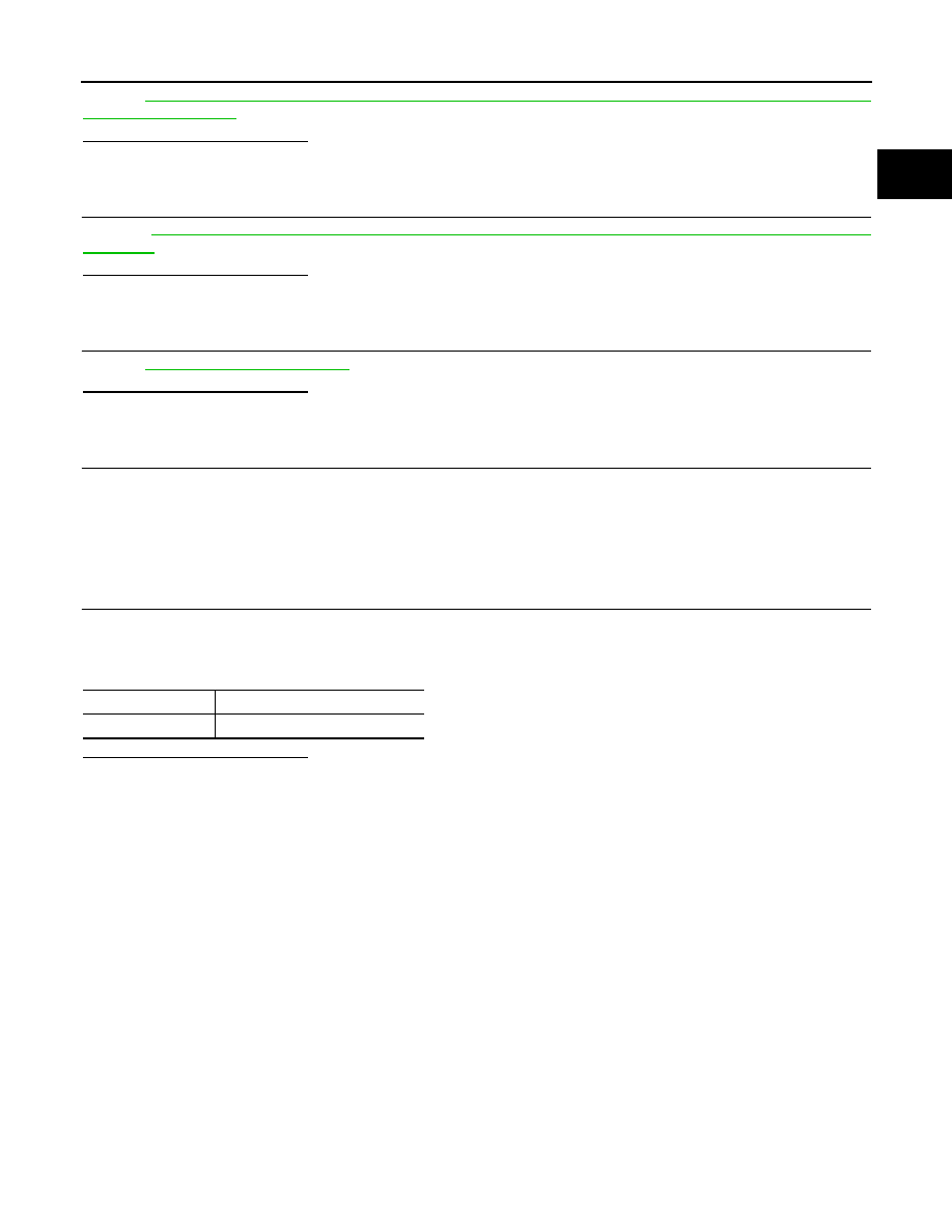
Terminals

Resistance

1 and 2

1.5 - 15

EC-1320

< COMPONENT DIAGNOSIS >

[K9K]

P0016 CKP - CMP CORRELATION

P0016 CKP - CMP CORRELATION

DTC Logic

INFOID:0000000001115053

DTC DETECTION LOGIC

NOTE:
• Conditions for applying the diagnostic procedure to the stored DTCs:

The DTC is declared present when cranking the engine or at idle speed.

• If the DTC is present:

Longer starting time, requires several attempts to start the vehicle.

Diagnosis Procedure

INFOID:0000000000952664

1.

CHECK GROUND CONNECTIONS

1.

Turn ignition switch OFF.

2.

 Check ground connection E17. Refer to Ground inspection in 

GI-41, "Circuit Inspection"

.

Is the inspection result normal?

YES

>> GO TO 2.

NO

>> Repair or replace ground connection.

2.

CHECK CMP SENSOR

1.

Turn ignition switch OFF.

2.

Disconnect camshaft position (CMP) sensor harness connector.

3.

Turn ignition switch ON.

4.

Check the voltage between CMP sensor harness connector and ground.

Is the inspection result normal?

YES

>> GO TO 4.

NO

>> GO TO 3.

3.

DETECT MALFUNCTIONING PART

Check the following.
• Harness connector E7, F121
• Harness for open or short between ECM and CMP sensor

>> Repair open circuit or short to ground or short to power in harness or connectors.

4.

CHECK CMP SENSOR GROUND CIRCUIT FOR OPEN AND SHORT

1.

Turn ignition switch OFF.

2.

Disconnect ECM harness connector.

3.

Check the continuity between CMP sensor harness connector and ECM harness connector.

DTC No.

Trouble diagnosis name

Possible cause

P0016

CRANKSHAFT POSITION - CAMSHAFT POSITION CORRELA-
TION

• Harness or connectors

(CMP sensor circuit is open or shorted.)

• Camshaft position sensor
• Timing belt
• Signal plate

CMP sensor

Ground

Voltage

Connector

Terminal

F87

3

Ground

Battery voltage

CMP sensor

ECM

Continuity

Connector

Terminal

Connector

Terminal

F87

1

F68

65

Existed

P0016 CKP - CMP CORRELATION

EC-1321

< COMPONENT DIAGNOSIS >

[K9K]

C

D

E

F

G

H

I

J

K

L

M

A

EC

N

P

O

4.

Also check harness for short to ground and short to power. 

Is the inspection result normal?

YES

>> GO TO 5.

NO

>> Repair open circuit or short to ground or short to power in harness or connectors.

5.

CHECK CMP SENSOR INPUT SIGNAL CIRCUIT FOR OPEN AND SHORT

1.

Check the continuity between CMP sensor harness connector and ECM harness connector.

2.

Also check harness for short to ground and short to power. 

Is the inspection result normal?

YES

>> GO TO 6.

NO

>> Repair open circuit or short to ground or short to power in harness or connectors.

6.

CHECK CMP SENSOR 

Refer to 

EC-1325, "Component Inspection"

.

Is the inspection result normal?

YES

>> GO TO 7.

NO

>> Replace camshaft position sensor.

7.

CHECK SPROCKET 

Visually check for chipping signal plate gear tooth.
Is the inspection result normal?

YES

>> GO TO 8.

NO

>> Repair or replace sprocket.

8.

CHECK TIMING BELT

Refer to 

EM-287, "Removal and Installation"

.

Is the inspection result normal?

YES

>> GO TO 9.

NO

>> Replace timing belt.

9.

CHECK INTERMITTENT INCIDENT

Refer to 

GI-39, "Intermittent Incident"

.

>> INSPECTION END

Component Inspection

INFOID:0000000001088003

1.

CHECK CMP SENSOR

1.

Reconnect all harness connectors disconnected.

2.

Start engine and warm it up to normal operating temperature.

3.

Measure the voltage signal between ECM harness connector and ground under the following conditions.

CMP sensor

ECM

Continuity

Connector

Terminal

Connector

Terminal

F87

2

F68

75

Existed

EC-1322

< COMPONENT DIAGNOSIS >

[K9K]

P0016 CKP - CMP CORRELATION

Is the inspection result normal?

YES

>> INSPECTION END

NO

>> Replace CMP sensor.

ECM

Condition

Voltage

Connector

Terminal

F68

75

(CMP sensor signal)

[Engine is running]
• Warm-up condition
• Idle speed

NOTE:
The pulse cycle changes de-
pending on rpm at idle.

0 - 1V 

[Engine is running]
• Warm-up condition
• Engine speed: 2,000 rpm

0 - 1V 

MBIB1510E

MBIB1511E


Content   ..  448  449  450  451   ..