Nissan Qashqai (2007-2010). Manual - part 336
 

  Index      Nissan     Nissan Qashqai - service and repair manual 2007 - 2010 year


Search            copyright infringement  


Content   ..  334  335  336  337   ..


Nissan Qashqai (2007-2010). Manual - part 336


P1147 HO2S2

EC-863

< COMPONENT DIAGNOSIS >

[MR20DE (WITH EURO-OBD)]

C

D

E

F

G

H

I

J

K

L

M

A

EC

N

P

O

7.

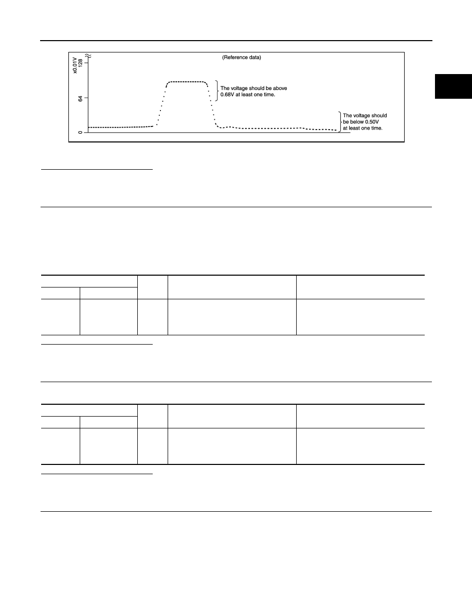
Check “HO2S2 (B1)” at idle speed when adjusting “FUEL INJECTION” to 

±

25%.

“HO2S2 (B1)” should be above 0.68V at least once when the “FUEL INJECTION” is +25%.
“HO2S2 (B1)” should be below 0.50V at least once when the “FUEL INJECTION” is 

25%.

Is the inspection result normal?

YES

>> INSPECTION END

NO

>> GO TO 6.

3.

CHECK HEATED OXYGEN SENSOR 2-I

Without CONSULT-III

1.

Start engine and warm it up to the normal operating temperature.

2.

Turn ignition switch OFF and wait at least 10 seconds.

3.

Start engine and keep the engine speed between 3,500 and 4,000 rpm for at least 1 minute under no load.

4.

Let engine idle for 1 minute.

5.

Check the voltage between ECM harness connector and ground under the following condition.

Is the inspection result normal?

YES

>> INSPECTION END

NO

>> GO TO 4.

4.

CHECK HEATED OXYGEN SENSOR 2-II

Check the voltage between ECM harness connector and ground under the following condition.

Is the inspection result normal?

YES

>> INSPECTION END

NO

>> GO TO 5.

5.

CHECK HEATED OXYGEN SENSOR 2-III

Check the voltage between ECM harness connector and ground under the following condition.

PBIB0551E

ECM

Ground

Condition

Voltage

Connector

Terminal

F8

50

(HO2S2 signal)

Ground

Revving up to 4,000 rpm under no load at 
least 10 times

The voltage should be above 0.68V at 
least once during this procedure.
The voltage should be below 0.50V at least 
once during this procedure.

ECM

Ground

Condition

Voltage

Connector

Terminal

F8

50

(HO2S2 signal)

Ground

Keeping engine speed at idle for 10 min-
utes

The voltage should be above 0.68V at 
least once during this procedure.
The voltage should be below 0.50V at least 
once during this procedure.

EC-864

< COMPONENT DIAGNOSIS >

[MR20DE (WITH EURO-OBD)]

P1147 HO2S2

Is the inspection result normal?

YES

>> INSPECTION END

NO

>> GO TO 6.

6.

REPLACE HEATED OXYGEN SENSOR 2

Replace heated oxygen sensor 2.

CAUTION:

• Discard any heated oxygen sensor which has been dropped from a height of more than 0.5 m (19.7

in) onto a hard surface such as a concrete floor; use a new one.

• Before installing new oxygen sensor, clean exhaust system threads using Oxygen Sensor Thread

Cleaner tool and approved anti-seize lubricant.

>> INSPECTION END

ECM

Ground

Condition

Voltage

Connector

Terminal

F8

50

(HO2S2 signal)

Ground

Coasting from 80 km/h (50 MPH) in D po-
sition (CVT), 4th gear position (M/T)

The voltage should be above 0.68V at 
least once during this procedure.
The voltage should be below 0.50V at least 
once during this procedure.

P1211 TCS CONTROL UNIT

EC-865

< COMPONENT DIAGNOSIS >

[MR20DE (WITH EURO-OBD)]

C

D

E

F

G

H

I

J

K

L

M

A

EC

N

P

O

P1211 TCS CONTROL UNIT

Description

INFOID:0000000001089443

The malfunction information related to TCS is transferred through the CAN communication line from “ABS
actuator and electric unit (control unit)” to ECM.
Be sure to erase the malfunction information such as DTC not only for “ABS actuator and electric unit
(control unit)” but also for ECM after TCS related repair.

DTC Logic

INFOID:0000000001089444

DTC DETECTION LOGIC

Freeze frame data is not stored in the ECM for this self-diagnosis.

DTC CONFIRMATION PROCEDURE

1.

PRECONDITIONING

TESTING CONDITION:
Before performing the following procedure, confirm that battery voltage is more than 10.5V at idle.

>> GO TO 2.

2.

PERFORM DTC CONFIRMATION PROCEDURE

1.

Start engine and let it idle for at least 60 seconds.

2.

Check 1st trip DTC.

Is 1st trip DTC detected?

YES

>>

EC-868, "Diagnosis Procedure"

NO

>> INSPECTION END

Diagnosis Procedure

INFOID:0000000001089445

Go to 

BRC-74, "Work Flow"

.

DTC No.

Trouble diagnosis name

DTC detecting condition

Possible cause

P1211

TCS control unit

ECM receives a malfunction information from
“ABS actuator and electric unit (control unit)”.

• ABS actuator and electric unit (control 

unit)

• TCS related parts

EC-866

< COMPONENT DIAGNOSIS >

[MR20DE (WITH EURO-OBD)]

P1212 TCS COMMUNICATION LINE

P1212 TCS COMMUNICATION LINE

Description

INFOID:0000000001089446

This CAN communication line is used to control the smooth engine operation during the TCS operation. Pulse
signals are exchanged between ECM and “ABS actuator and electric unit (control unit)”.
Be sure to erase the malfunction information such as DTC not only for “ABS actuator and electric unit
(control unit)” but also for ECM after TCS related repair.

DTC Logic

INFOID:0000000001089447

DTC DETECTION LOGIC

NOTE:
• If DTC P1212 is displayed with DTC U1001, first perform the trouble diagnosis for DTC U1001. Refer

to 

EC-740, "DTC Logic"

.

• If DTC P1212 is displayed with DTC U1010, first perform the trouble diagnosis for DTC U1010. Refer

to 

EC-741, "DTC Logic"

.

Freeze frame data is not stored in the ECM for this self-diagnosis.

DTC CONFIRMATION PROCEDURE

1.

PRECONDITIONING

TESTING CONDITION:
Before performing the following procedure, confirm that battery voltage is more than 10.5V at idle.

>> GO TO 2.

2.

PERFORM DTC CONFIRMATION PROCEDURE

1.

Start engine and let it idle for at least 10 seconds.

2.

Check 1st trip DTC.

Is 1st trip DTC detected?

YES

>> Go to 

EC-869, "Diagnosis Procedure"

.

NO

>> INSPECTION END

Diagnosis Procedure

INFOID:0000000001089448

Go to 

BRC-74, "Work Flow"

.

DTC No.

Trouble diagnosis name

DTC detecting condition

Possible cause

P1212

TCS communication line

ECM can not receive the information from 
“ABS actuator and electric unit (control 
unit)” continuously.

• Harness or connectors

(The CAN communication line is open or short-
ed.)

• ABS actuator and electric unit (control unit)
• Dead (Weak) battery


Content   ..  334  335  336  337   ..