Nissan Qashqai (2007-2010). Manual - part 247
 

  Index      Nissan     Nissan Qashqai - service and repair manual 2007 - 2010 year


Search            copyright infringement  


Content   ..  245  246  247  248   ..


Nissan Qashqai (2007-2010). Manual - part 247


P1128 THROTTLE CONTROL MOTOR

EC-507

< COMPONENT DIAGNOSIS >

[HR16DE (WITHOUT EURO-OBD)]

C

D

E

F

G

H

I

J

K

L

M

A

EC

N

P

O

P1128 THROTTLE CONTROL MOTOR

Description

INFOID:0000000001096891

The throttle control motor is operated by the ECM and it opens and closes the throttle valve.
The current opening angle of the throttle valve is detected by the throttle position sensor and it provides feed-
back to the ECM to control the throttle control motor to make the throttle valve opening angle properly in
response to driving condition.

DTC Logic

INFOID:0000000001096892

DTC DETECTION LOGIC

DTC CONFIRMATION PROCEDURE

1.

PRECONDITIONING

If DTC Confirmation Procedure has been previously conducted, always turn ignition switch OFF and wait at
least 10 seconds before conducting the next test.

>> GO TO 2.

2.

PERFORM DTC CONFIRMATION PROCEDURE

1.

Turn ignition switch ON and wait at least 2 seconds.

2.

Start engine and let it idle for 5 seconds.

3.

Check DTC.

Is DTC detected?

YES

>> Go to 

EC-508, "Diagnosis Procedure"

.

NO

>> INSPECTION END

Diagnosis Procedure

INFOID:0000000001096893

1.

CHECK GROUND CONNECTION

1.

Turn ignition switch OFF.

2.

Check ground connection E21. Refer to Ground Inspection in 

GI-41, "Circuit Inspection"

Is the inspection result normal?

YES

>> GO TO 2.

NO

>> Repair or replace ground connection.

2.

CHECK THROTTLE CONTROL MOTOR OUTPUT SIGNAL CIRCUIT FOR OPEN AND SHORT

1.

Disconnect electric throttle control actuator harness connector.

2.

Disconnect ECM harness connector.

3.

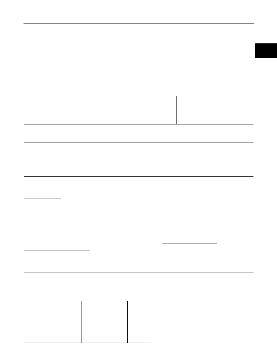
Check the continuity between electric throttle control actuator harness connector and ECM harness con-
nector.

DTC No.

Trouble diagnosis name

DTC detecting condition

Possible cause

P1128

Throttle control motor 
circuit short

ECM detects short in both circuits between 
ECM and throttle control motor.

• Harness or connectors

(Throttle control motor circuit is shorted.)

• Electric throttle control actuator

(Throttle control motor)

Electric throttle control actuator

ECM

Continuity

Connector

Terminal

Connector

Terminal

F29

5

F7

1

Not  existed

4

Existed

6

1

Existed

4

Not  existed

EC-508

< COMPONENT DIAGNOSIS >

[HR16DE (WITHOUT EURO-OBD)]

P1128 THROTTLE CONTROL MOTOR

4.

Also check harness for short to ground and short to power.

Is the inspection result normal?

YES

>> GO TO 3.

NO

>> Repair or replace.

3.

CHECK THROTTLE CONTROL MOTOR

Refer to 

EC-509, "Component Inspection"

.

Is the inspection result normal?

YES

>> GO TO 4.

NO

>> GO TO 5.

4.

CHECK INTERMITTENT INCIDENT

Refer to 

GI-39, "Intermittent Incident"

.

Is the inspection result normal?

YES

>> GO TO 5.

NO

>> Repair or replace harness or connectors.

5.

REPLACE ELECTRIC THROTTLE CONTROL ACTUATOR

1.

Replace electric throttle control actuator.

2.

Go to 

EC-509, "Special Repair Requirement"

.

>> INSPECTION END

Component Inspection

INFOID:0000000001096894

1.

CHECK THROTTLE CONTROL MOTOR

1.

Disconnect electric throttle control actuator harness connector.

2.

Check resistance between electric throttle control actuator terminals as follows.

Is the inspection result normal?

YES

>> INSPECTION END

NO

>> GO TO 2.

2.

REPLACE ELECTRIC THROTTLE CONTROL ACTUATOR

1.

Replace electric throttle control actuator.

2.

Go to 

EC-509, "Special Repair Requirement"

.

>> INSPECTION END

Special Repair Requirement

INFOID:0000000001096895

1.

PERFORM THROTTLE VALVE CLOSED POSITION LEARNING

Refer to 

EC-370, "THROTTLE VALVE CLOSED POSITION LEARNING : Special Repair Requirement"

>> GO TO 2.

2.

PERFORM IDLE AIR VOLUME LEARNING

Refer to 

EC-370, "IDLE AIR VOLUME LEARNING : Special Repair Requirement"

>> END

Terminals

Resistance [at 25 

°

C (77

°

F)]

5 and 6

Approx. 1 - 15 

P1212 TCS COMMUNICATION LINE

EC-509

< COMPONENT DIAGNOSIS >

[HR16DE (WITHOUT EURO-OBD)]

C

D

E

F

G

H

I

J

K

L

M

A

EC

N

P

O

P1212 TCS COMMUNICATION LINE

Description

INFOID:0000000001116301

This CAN communication line is used to control the smooth engine operation during the TCS operation. Pulse
signals are exchanged between ECM and “ABS actuator and electric unit (control unit)”.
Be sure to erase the malfunction information such as DTC not only for “ABS actuator and electric unit
(control unit)” but also for ECM after TCS related repair.

DTC Logic

INFOID:0000000001116302

DTC DETECTION LOGIC

NOTE:
• If DTC P1212 is displayed with DTC U1001, first perform the trouble diagnosis for DTC U1001. Refer

to 

EC-450, "DTC Logic"

.

• If DTC P1212 is displayed with DTC U1010, first perform the trouble diagnosis for DTC U1010. Refer

to 

EC-450, "DTC Logic"

.

Freeze frame data is not stored in the ECM for this self-diagnosis.

DTC CONFIRMATION PROCEDURE

1.

PRECONDITIONING

TESTING CONDITION:
Before performing the following procedure, confirm that battery voltage is more than 10.5V at idle.

>> GO TO 2.

2.

PERFORM DTC CONFIRMATION PROCEDURE

1.

Start engine and let it idle for at least 10 seconds.

2.

Check 1st trip DTC.

Is 1st trip DTC detected?

YES

>> Go to 

EC-510, "Diagnosis Procedure"

.

NO

>> INSPECTION END

Diagnosis Procedure

INFOID:0000000001116303

Go to 

BRC-6, "Work Flow"

.

DTC No.

Trouble diagnosis name

DTC detecting condition

Possible cause

P1212

TCS communication line

ECM can not receive the information from 
“ABS actuator and electric unit (control 
unit)” continuously.

• Harness or connectors

(The CAN communication line is open or short-
ed.)

• ABS actuator and electric unit (control unit)
• Dead (Weak) battery

EC-510

< COMPONENT DIAGNOSIS >

[HR16DE (WITHOUT EURO-OBD)]

P1217 ENGINE OVER TEMPERATURE

P1217 ENGINE OVER TEMPERATURE

DTC Logic

INFOID:0000000001096914

DTC DETECTION LOGIC

NOTE:
• If DTC P1217 is displayed with DTC U1001, first perform the trouble diagnosis for DTC U1001. Refer

to 

EC-450, "DTC Logic"

.

• If DTC P1217 is displayed with DTC U1010, first perform the trouble diagnosis for DTC U1010. Refer

to 

EC-451, "DTC Logic"

.

If the cooling fan or another component in the cooling system malfunctions, engine coolant temperature will
rise.
When the engine coolant temperature reaches an abnormally high temperature condition, a malfunction is
indicated.

CAUTION:

When a malfunction is indicated, be sure to replace the coolant. Refer to 

CO-9, "Inspection"

. Also,

replace the engine oil. Refer to 

LU-6, "Inspection"

.

1.

Fill radiator with coolant up to specified level with a filling speed of 2 liters per minute. Be sure to
use coolant with the proper mixture ratio. Refer to 

LU-6, "Inspection"

.

2.

After refilling coolant, run engine to ensure that no water-flow noise is emitted.

DTC CONFIRMATION PROCEDURE

1.

PERFORM COMPONENT FUNCTION CHECK

Perform component function check. Refer to 

EC-511, "Component Function Check"

.

NOTE:
Use component function check to check the overall function of the cooling fan. During this check, a DTC might
not be confirmed.
Is the inspection result normal?

YES

>> INSPECTION END

NO

>> Go to 

EC-512, "Diagnosis Procedure"

.

Component Function Check

INFOID:0000000001096915

1.

PERFORM COMPONENT FUNCTION CHECK-I

WARNING:

Never remove the radiator cap when the engine is hot. Serious burns could be caused by high pres-
sure fluid escaping from the radiator.
Wrap a thick cloth around cap. Carefully remove the cap by turning it a quarter turn to allow built-up
pressure to escape. Then turn the cap all the way off.

DTC No.

Trouble diagnosis name

DTC detecting condition

Possible cause

P1217

Engine over tempera-
ture (Overheat)

• Cooling fan does not operate properly (Over-

heat).

• Cooling fan system does not operate proper-

ly (Overheat).

• Engine coolant was not added to the system 

using the proper filling method.

• Engine coolant is not within the specified 

range.

• Harness or connectors

(The cooling fan circuit is open or short-
ed.)

• IPDM E/R (Cooling fan relays -1 and -3)
• Cooling fan motor
• Radiator  hose
• Radiator
• Radiator  cap
• Reservoir tank
• Water pump
• Thermostat


Content   ..  245  246  247  248   ..