Nissan Qashqai (2007-2010). Manual - part 221
 

  Index      Nissan     Nissan Qashqai - service and repair manual 2007 - 2010 year


Search            copyright infringement  


Content   ..  219  220  221  222   ..


Nissan Qashqai (2007-2010). Manual - part 221


AUTOMATIC SPEED CONTROL DEVICE (ASCD)

EC-403

< FUNCTION DIAGNOSIS >

[HR16DE (WITHOUT EURO-OBD)]

C

D

E

F

G

H

I

J

K

L

M

A

EC

N

P

O

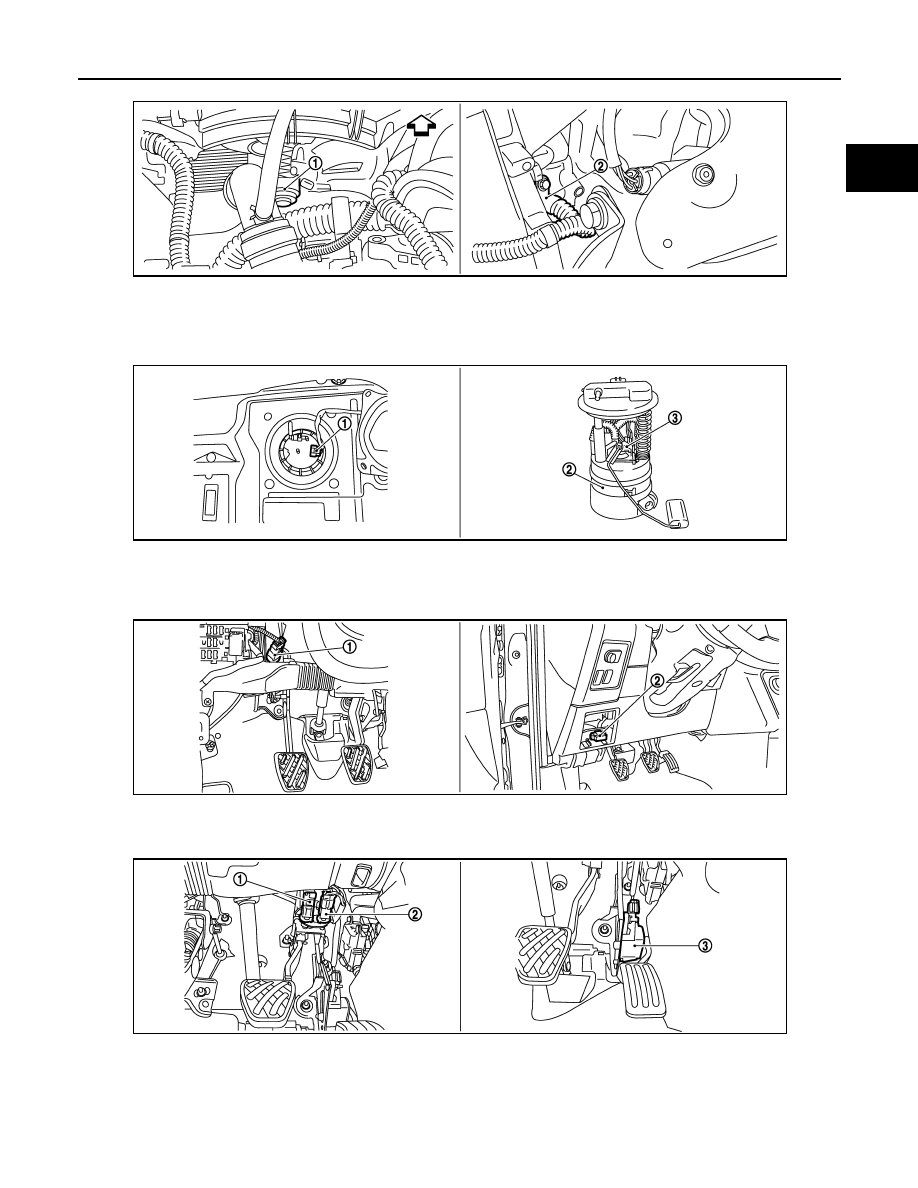
1.

Cooling fan motor

2.

Crankshaft position sensor (POS)

Vehicle front

1.

Fuel level sensor unit and fuel pump 
harness connector

2.

Fuel level sensor unit and fuel pump  3.

Fuel pressure regulator

1.

ASCD clutch switch

2.

Data link connector 

1.

Stop lamp switch

2.

ASCD brake pedal

3.

Accelerator pedal position sensor

JMBIA0407ZZ

JMBIA0346ZZ

JMBIA0347ZZ

JMBIA0348ZZ

EC-404

< FUNCTION DIAGNOSIS >

[HR16DE (WITHOUT EURO-OBD)]

AUTOMATIC SPEED CONTROL DEVICE (ASCD)

Component Description

INFOID:0000000001096759

1.

ASCD steering switch

2.

CANSEL switch

3.

RESUME/ACCELERATE switch

4.

SET/COAST switch

5.

MAIN switch

JMBIA0349ZZ

Component

Reference

ASCD steering switch

EC-263, "Description"

ASCD clutch switch

EC-553, "Description"

ASCD brake switch

EC-294, "Description"

ASCD indicator

EC-557, "Description"

Stop lamp switch

EC-536, "Description"

Electric throttle control actuator

EC-499, "Description"

CAN COMMUNICATION

EC-405

< FUNCTION DIAGNOSIS >

[HR16DE (WITHOUT EURO-OBD)]

C

D

E

F

G

H

I

J

K

L

M

A

EC

N

P

O

CAN COMMUNICATION

System Description

INFOID:0000000001096760

CAN (Controller Area Network) is a serial communication line for real time application. It is an on-vehicle mul-
tiplex communication line with high data communication speed and excellent error detection ability. Many elec-
tronic control units are equipped onto a vehicle, and each control unit shares information and links with other
control units during operation (not independent). In CAN communication, control units are connected with 2
communication lines (CAN H line, CAN L line) allowing a high rate of information transmission with less wiring.
Each control unit transmits/receives data but selectively reads required data only.
Refer to 

LAN-59, "CAN Communication Signal Chart"

, about CAN communication for detail.

EC-406

< FUNCTION DIAGNOSIS >

[HR16DE (WITHOUT EURO-OBD)]

COOLING FAN CONTROL

COOLING FAN CONTROL

System Diagram

INFOID:0000000001096761

System Description

INFOID:0000000001096762

INPUT/OUTPUT SIGNAL CHART

*1: The ECM determines the start signal status by the signals of engine speed and battery voltage.

*2: This signal is sent to ECM through CAN communication line.

SYSTEM DESCRIPTION

ECM controls cooling fan speed corresponding to vehicle speed, engine coolant temperature, refrigerant pres-
sure, air conditioner ON signal. Then control system has 3-step control [HIGH/LOW/OFF].

Cooling Fan Operation

JMBIA0177GB

Sensor

Input signal to ECM

ECM function

Actuator

Crankshaft position sensor (POS)
Camshaft position sensor (PHASE)

Engine speed*

1

Cooling fan 
control

IPDM E/R

Cooling fan relay

Cooling fan motor

Battery

Battery voltage*

1

Combination meter

Vehicle speed*

2

Engine coolant temperature sensor

Engine coolant temperature

BCM

Air conditioner ON signal*

2

Refrigerant pressure sensor

Refrigerant pressure

JMBIA0412GB


Content   ..  219  220  221  222   ..