Nissan Qashqai (2007-2010). Manual - part 1963


  Index      Nissan     Nissan Qashqai - service and repair manual 2007 - 2010 year


Search            copyright infringement  


Content   ..  1961  1962  1963  1964   ..


Nissan Qashqai (2007-2010). Manual - part 1963


AV-110

< COMPONENT DIAGNOSIS >

[AUDIO WITH NAVIGATION]

MICROPHONE SIGNAL CIRCUIT

MICROPHONE SIGNAL CIRCUIT

Description

INFOID:0000000000947108

Supplies power from NAVI control unit to microphone. The microphone transmits the sound voice to the NAVI
control unit.

Diagnosis Procedure

INFOID:0000000000947109

1.

CHECK CONTINUITY BETWEEN NAVI CONTROL UNIT AND MICROPHONE CIRCUIT

1.

Turn ignition switch OFF.

2.

Disconnect NAVI control unit connector and microphone connector.

3.

Check continuity between NAVI control unit harness connector terminals 6, 7, 8 and microphone harness
connector terminals 4, 2, 1.

4.

Check continuity between NAVI control unit harness connector terminals 6, 8 and ground.

Is inspection result OK?

YES

>> GO TO 2.

NO

>> Repair harness or connector.

2.

CHECK VOLTAGE MICROPHONE VCC 

1.

Connect NAVI control unit connector.

2.

Turn ignition switch ON.

3.

Check voltage between NAVI control unit harness connector terminals 6 and 7.

Is inspection result OK?

YES

>> GO TO 3.

NO

>> Replace NAVI control unit.

3.

CHECK MICROPHONE SIGNAL 

1.

Connect microphone connector.

2.

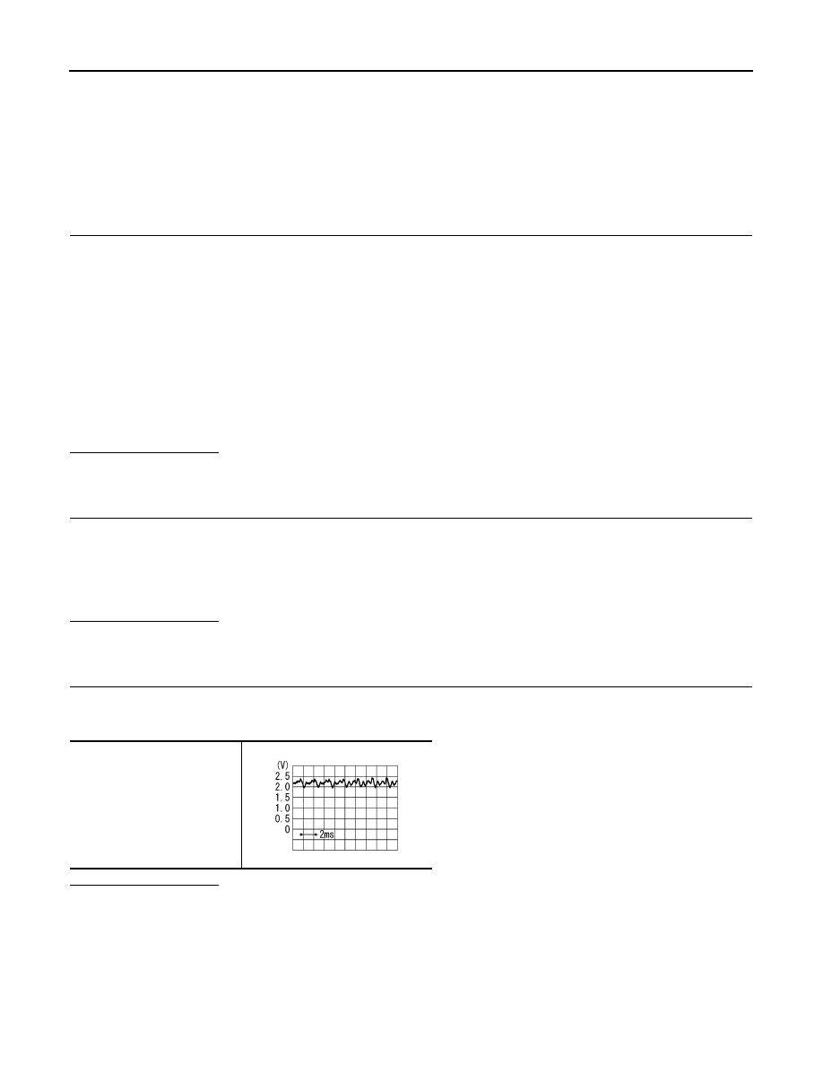
Check signal between NAVI control unit harness connector terminals 8 and 7.

Is inspection result OK?

YES

>> Replace NAVI control unit.

NO

>> Replace microphone.

6 - 4

: Continuity should exist.

7 - 2

: Continuity should exist.

8 - 1

: Continuity should exist.

6, 8 - Ground

: Continuity should not exist.

6 - 7

: Approx. 5 V

8 - 7

PKIB5037J

AV

CAMERA IMAGE SIGNAL CIRCUIT (REAR VIEW CAMERA TO CAMERA CON-

TROL UNIT)

AV-111

< COMPONENT DIAGNOSIS >

[AUDIO WITH NAVIGATION]

C

D

E

F

G

H

I

J

K

L

M

B

A

O

P

CAMERA IMAGE SIGNAL CIRCUIT (REAR VIEW CAMERA TO CAMERA
CONTROL UNIT)

Description

INFOID:0000000000947110

• Camera control unit outputs camera ON signal to rear view camera and inputs rear view camera image sig-

nal from rear view camera when the reverse signal is input.

• The camera control unit that inputs the camera image signal transmits the camera image signal to the dis-

play unit.

Diagnosis Procedure

INFOID:0000000000947111

1.

CHECK CONTINUITY CAMERA IMAGE SIGNAL CIRCUIT

1.

Turn ignition switch OFF.

2.

Disconnect camera control unit connector and rear view camera connector.

3.

Check continuity between camera control unit harness connector terminal 10 and rear view camera har-
ness connector terminal 3.

4.

Check continuity between camera control unit harness connector terminal 10 and ground.

Is inspection result OK?

YES

>> GO TO 2.

NO

>> Repair harness or connector.

2.

CHECK CAMERA IMAGE SIGNAL

1.

Connect camera control unit connector and rear view camera connector.

2.

Turn ignition switch ON.

3.

Check signal between camera control unit harness connector terminal 10 and ground.

Is inspection result OK?

YES

>> Replace camera control unit.

NO

>> Replace rear view camera.

10 - 3

: Continuity should exist.

10 - Ground

: Continuity should not exist.

10 - Ground

At rear view camera image displayed

SKIB0827E

AV-112

< COMPONENT DIAGNOSIS >

[AUDIO WITH NAVIGATION]

CAMERA IMAGE SIGNAL CIRCUIT (CAMERA CONTROL UNIT TO DISPLAY 

UNIT)

CAMERA IMAGE SIGNAL CIRCUIT (CAMERA CONTROL UNIT TO DIS-
PLAY UNIT)

Description

INFOID:0000000000947114

• Camera control unit outputs camera ON signal to rear view camera and inputs rear view camera image sig-

nal from rear view camera when the reverse signal is input.  

• The camera control unit that inputs the camera image signal transmits the camera image signal to the dis-

play unit.

Diagnosis Procedure

INFOID:0000000000947115

1.

CHECK CONTINUITY CAMERA IMAGE SIGNAL CIRCUIT

1.

Turn ignition switch OFF.

2.

Disconnect camera control unit connector and display unit connector.

3.

Check continuity between camera control unit harness connector terminal 12, 11 and display unit harness
connector terminal 11, 12.

4.

Check continuity between camera control unit harness connector terminal 12 and ground.

Is inspection result OK?

YES

>> GO TO 2.

NO

>> Repair harness or connector.

2.

CHECK CAMERA IMAGE SIGNAL

1.

Connect camera control unit connector and display unit connector.

2.

Turn ignition switch ON.

3.

Check signal between camera control unit harness connector terminal 12 and ground.

Is inspection result OK?

YES

>> Replace display unit.

NO

>> Replace camera control unit.

12 - 11

: Continuity should exist.

11 - 12

: Continuity should exist.

12 - Ground

: Continuity should not exist.

12 - Ground

At rear view camera image displayed

SKIB0827E

AV

CAMERA ON SIGNAL CIRCUIT

AV-113

< COMPONENT DIAGNOSIS >

[AUDIO WITH NAVIGATION]

C

D

E

F

G

H

I

J

K

L

M

B

A

O

P

CAMERA ON SIGNAL CIRCUIT

Description

INFOID:0000000000947112

• Camera control unit outputs camera ON signal to rear view camera and inputs rear view camera image sig-

nal from rear view camera when the reverse signal is input.  

• The camera control unit that inputs the camera image signal transmits the camera image signal to the dis-

play unit.

Diagnosis Procedure

INFOID:0000000000947113

1.

CHECK CONTINUITY CAMERA ON SIGNAL CIRCUIT

1.

Turn ignition switch OFF.

2.

Disconnect camera control unit connector and rear view camera connector.

3.

Check continuity between camera control unit harness connector terminal 8 and rear view camera har-
ness connector terminal 1.

4.

Check continuity between camera control unit harness connector terminal 8 and ground.

Is inspection result OK?

YES

>> GO TO 2.

NO

>> Repair harness or connector.

2.

CHECK VOLTAGE CAMERA ON SIGNAL

1.

Connect camera control unit connector and rear view camera connector.

2.

Turn ignition switch ON.

3.

Shift the selector lever to “R” position.

4.

Check signal between camera control unit harness connector terminal 8 and ground.

Is inspection result OK?

YES

>> Replace rear view camera.

NO

>> Replace camera control unit.

8 - 1

: Continuity should exist.

8 - Ground

: Continuity should not exist.

8 - Ground

: Approx. 6 V


Content   ..  1961  1962  1963  1964   ..