Content .. 1485 1486 1487 1488 ..
Nissan Qashqai (2007-2010). Manual - part 1487
BCS-38
< COMPONENT DIAGNOSIS >
COMBINATION SWITCH
COMBINATION SWITCH
Description
INFOID:0000000001026782
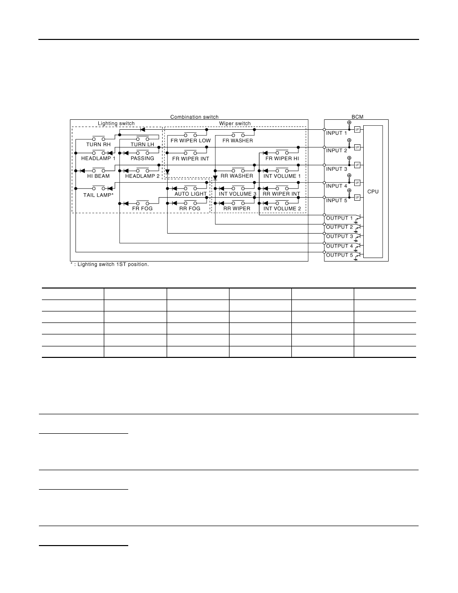
COMBINATION SWITCH MATRIX
Combination switch consists of INPUT circuit and OUTPUT circuit.
Combination switch circuit
Combination switch INPUT-OUTPUT system list
NOTE:
Headlamp has a dual system switch.
Diagnosis Procedure
INFOID:0000000001026783
1.
CHECK LIGHT & TURN SIGNAL SWITCH
Check operation with normal light & turn signal switch installed.
Does it operate normally?
YES
>> Replace light & turn signal switch.
NO
>> GO TO 2.
2.
CHECK WIPER & WASHER SWITCH
Check operation with normal wiper & washer switch installed.
Does it operate normally?
YES
>> Replace wiper & washer switch.
NO
>> GO TO 3.
3.
CHECK SWITCH BASE (SPIRAL CABLE)
Check operation with normal switch base (spiral cable) installed.
Does it operate normally?
YES
>> Replace switch base (spiral cable).
NO
>> Combination switch is normal.
System
OUTPUT 1
OUTPUT 2
OUTPUT 3
OUTPUT 4
OUTPUT 5
INPUT 1
—
FR WASHER
FR WIPER LOW
TURN LH
TURN RH
INPUT 2
FR WIPER HI
—
FR WIPER INT
PASSING
HEADLAMP 1
INPUT 3
INT VOLUME 1
RR WASHER
—
HEADLAMP 2
HI BEAM
INPUT 4
RR WIPER INT
INT VOLUME 3
AUTO LIGHT
—
TAIL LAMP
INPUT 5
INT VOLUME 2
RR WIPER
RR FOG
FR FOG
—
JPMIA0121GB