Nissan Qashqai (2007-2010). Manual - part 1278


  Index      Nissan     Nissan Qashqai - service and repair manual 2007 - 2010 year


Search            copyright infringement  


Content   ..  1276  1277  1278  1279   ..


Nissan Qashqai (2007-2010). Manual - part 1278


ENCODER CIRCUIT

PWC-29

< COMPONENT DIAGNOSIS >

C

D

E

F

G

H

I

J

L

M

A

B

PWC

N

O

P

():RHD models
Is the inspection result normal?

YES

>> GO TO 4.

NO

>> GO TO 3.

3.

CHECK HARNESS CONTINUITY 1

1.

Turn ignition switch OFF.

2.

Disconnect power window main switch connector and front power window motor (driver side) connector.

3.

Check continuity between power window main switch connector and front power window motor (driver
side) connector.

4.

Check continuity between power window main switch connector and ground.

():RHD models
Is the inspection result normal?

YES

>> Replace power window main switch. Refer to 

PWC-83, "Exploded View"

. After that, Refer to

PWC-15, "POWER WINDOW MAIN SWITCH : Special Repair Requirement"

.

NO

>> Repair or replace harness.

4.

CHECK GROUND CIRCUIT

1.

Turn ignition switch OFF.

2.

Disconnect front power window motor (driver side) connector.

3.

Check continuity between front power window motor (driver side) connector and ground.

():RHD models
Is the inspection result normal?

YES

>> GO TO 6.

NO

>> GO TO 5.

5.

CHECK HARNESS CONTINUITY 2

1.

Disconnect power window main switch connector.

2.

Check continuity between power window main switch connector and front power window motor (driver
side) connector.

():RHD models

Is the inspection result normal?

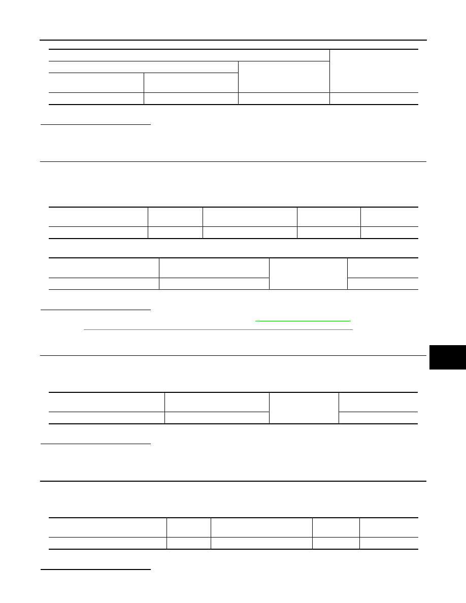
Terminal

Voltage (V)

(Approx.)

(+)

(–)

 Front power window motor 

(driver side) connector

Terminal 

D7 (D27)

5

Ground

10

Power window main switch con-

nector

Terminal

Front power window motor 

(driver side) connector

Terminal

Continuity

D5 (D25)

15

D7 (D27)

5

Existed

Power window main switch connec-

tor

Terminal

Ground

Continuity

D5 (D25)

15

Not existed

Front power window motor (driver 

side) connector

Terminal

Ground

Continuity 

D7 (D27)

2

Existed

Power window main switch connector

Terminal

Front power window motor (driver 

side) connector

Terminal

Continuity

D5 (D25)

2

D7 (D27)

2

Existed

PWC-30

< COMPONENT DIAGNOSIS >

ENCODER CIRCUIT

YES

>> Replace power window main switch. Refer to 

PWC-83, "Exploded View"

. After that, Refer to

PWC-15, "POWER WINDOW MAIN SWITCH : Special Repair Requirement"

.

NO

>> Repair or replace harness.

6.

CHECK HARNESS CONTINUITY 3

1.

Disconnect power window main switch connector.

2.

Check continuity between power window main switch connector and front power window motor (driver
side) connector.

3.

Check continuity between power window main switch connector and ground.

():RHD models
Is the inspection result normal?

YES

>> Replace front power window motor (driver side). Refer to 

GW-22, "Exploded View"

 and 

GW-22,

"Removal and Installation"

. After that, Refer to 

PWC-22, "DRIVER SIDE : Special Repair Require-

ment"

.

NO

>> Repair or replace harness.

Power window main switch connector

Terminal

Front power window motor (driver 

side) connector

Terminal

Continuity

D5 (D25)

9

D7 (D27)

1

Existed

13

6

Power window main switch connec-

tor

Terminal

Ground

Continuity

D5 (D25)

9

Not existed

13

POWER WINDOW LOCK SWITCH

PWC-31

< COMPONENT DIAGNOSIS >

C

D

E

F

G

H

I

J

L

M

A

B

PWC

N

O

P

POWER WINDOW LOCK SWITCH

Description

INFOID:0000000000990520

Ground circuit of power window main switch shuts off if power window lock switch of power window main
switch is operated. This inhibits all operation, except for the main switch.

Component Function Check

INFOID:0000000000990521

1.

CHECK POWER WINDOW LOCK SIGNAL

Exchanges for a normal power window main switch, and operation is checked.
Does power window lock operate?

YES

>> Replace power window main switch. Refer to 

PWC-83, "Exploded View"

. After that

PWC-31,

"Special Repair Requirement"

NO

>> Check condition of harness and connector.

Special Repair Requirement

INFOID:0000000000990522

1.

PERFORM INITIALIZATION PROCEDURE

Perform initialization procedure. 
Refer to 

PWC-4, "ADDITIONAL SERVICE WHEN REPLACING CONTROL UNIT : Special Repair Require-

ment"

.

Is the inspection result normal?

YES

>> GO TO 2.

NO

>> Check intermittent incident. Refer to 

GI-39, "Intermittent Incident"

.

2.

CHECK ANTI-PINCH OPERATION

Check anti-pinch operation. 
Refer to 

PWC-4, "ADDITIONAL SERVICE WHEN REPLACING CONTROL UNIT : Special Repair Require-

ment"

.

Is the inspection result normal?

YES

>> Inspection end.

NO

>> Refer to 

PWC-28, "DRIVER SIDE : Component Function Check"

PWC-32

< ECU DIAGNOSIS >

BCM (BODY CONTROL MODULE)

ECU DIAGNOSIS

BCM (BODY CONTROL MODULE)

Reference Value

INFOID:0000000001116528

VALUES ON THE DIAGNOSIS TOOL

Monitor Item

Condition

Value/Status

ACC ON SW

Ignition switch OFF

OFF

Ignition switch ACC or ON

ON

AIR COND SW

A/C switch OFF

OFF

A/C switch ON

ON

AUT LIGHT SYS

Outside of the room is dark

OFF

Outside of the room is bright

ON

AUTO LIGHT SW

Lighting switch OFF

OFF

Lighting switch AUTO

ON

BACK DOOR SW

Back door closed

OFF

Back door opened

ON

BATTERY VOLT
NOTE:
Diesel engine models 
only

Ignition switch ON

Approximately the same as power 
supply voltage

BUCKLE SW

Driver's seat belt unfastened

OFF

Driver's seat belt fastened

ON

CDL LOCK SW

Door lock/unlock switch does not operate

OFF

Press door lock/unlock switch to the LOCK side

ON

CDL UNLOCK SW

Door lock/unlock switch does not operate

OFF

Press door lock/unlock switch to the UNLOCK side

ON

DOOR SW-AS

Passenger door closed

OFF

Passenger door opened

ON

DOOR SW-DR

Driver door closed

OFF

Driver door opened

ON

DOOR SW-RL

Rear LH door closed

OFF

Rear LH door opened

ON

DOOR SW-RR

Rear RH door closed

OFF

Rear RH door opened

ON

ELEC PWR CUT
NOTE:
Diesel engine models 
only

Engine running

Fan switch ON (when engine coolant is 
cool)
NOTE:
Depending on the ambient tempera-
ture, battery voltage, etc.

OFF

The current status maintained with the 
signal from ECM received.

FREEZ

• Fan switch OFF
• Fan switch ON after engine warming 

UP
NOTE:
Depending on the engine coolant 
temperature, ambient temperature, 
battery voltage, etc.

INHBT


Content   ..  1276  1277  1278  1279   ..