Nissan Qashqai (2007-2010). Manual - part 1274


  Index      Nissan     Nissan Qashqai - service and repair manual 2007 - 2010 year


Search            copyright infringement  


Content   ..  1272  1273  1274  1275   ..


Nissan Qashqai (2007-2010). Manual - part 1274


POWER SUPPLY AND GROUND CIRCUIT

PWC-13

< COMPONENT DIAGNOSIS >

C

D

E

F

G

H

I

J

L

M

A

B

PWC

N

O

P

NO

>> Replace power window main switch. Refer to 

PWC-83, "Exploded View"

. After that, Refer to

PWC-15, "POWER WINDOW MAIN SWITCH : Special Repair Requirement"

.

9.

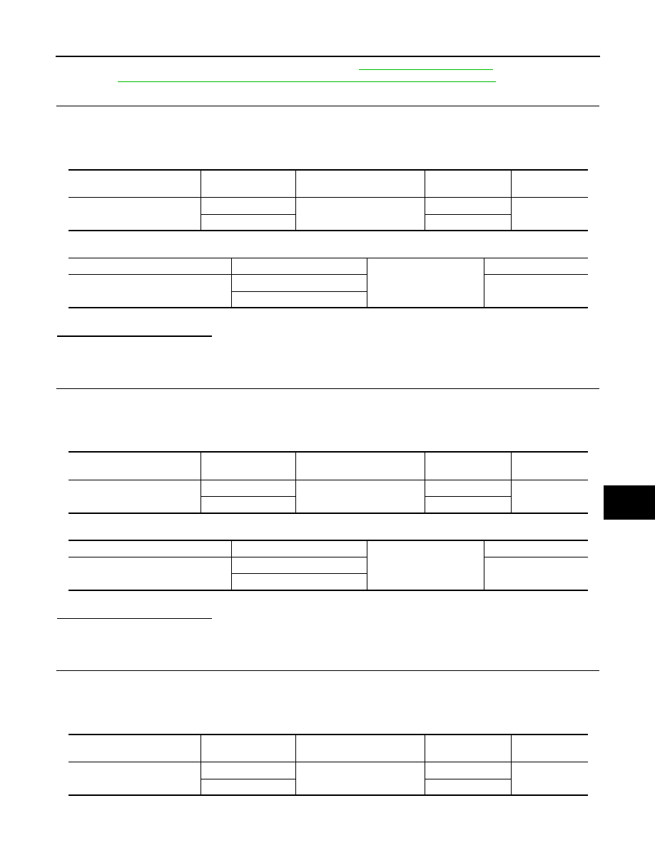
CHECK HARNESS CONTINUITY (FRONT POWER WINDOW SWITCH PASSENGER SIDE)

1.

Turn ignition switch OFF.

2.

Disconnect rear power window switch LH connector.

3.

Check continuity between power window main switch connector and rear power window switch LH con-
nector.

4.

Check continuity between power window main switch connector and ground.

():RHD models

Is the inspection result normal?

YES

>> GO TO 12.

NO

>> Repair or replace harness.

10.

CHECK HARNESS CONTINUITY (REAR POWER WINDOW SWITCH LH)

1.

Turn ignition switch OFF.

2.

Disconnect rear power window switch LH connector.

3.

Check continuity between power window main switch connector and rear power window switch LH con-
nector.

4.

Check continuity between power window main switch connector and ground.

():RHD models

Is the inspection result normal?

YES

>> GO TO 12.

NO

>> Repair or replace harness.

11.

CHECK HARNESS CONTINUITY (REAR POWER WINDOW SWITCH RH)

1.

Turn ignition switch OFF.

2.

Disconnect rear power window switch RH connector.

3.

Check continuity between power window main switch connector and rear power window switch RH con-
nector.

4.

Check continuity between power window main switch connector and ground.

Power window main switch 

connector

Terminal

Front power window switch 

(passenger side) connector

Terminal

Continuity

D5 (D25)

8

D45 (D65)

2

Existed

11

3

Power window main switch connector

Terminal

Ground

Continuity

D5 (D25)

8

Not existed

11

Power window main switch 

connector

Terminal

Rear power window switch LH 

connector

Terminal

Continuity

D5 (D25)

1

D83 (D113)

2

Existed

3

3

Power window main switch connector

Terminal

Ground

Continuity

D5 (D25)

1

Not existed

3

Power window main switch 

connector

Terminal

Rear power window switch 

RH connector

Terminal

Continuity

D5 (D25)

5

D103 (D93)

3

Existed

7

2

PWC-14

< COMPONENT DIAGNOSIS >

POWER SUPPLY AND GROUND CIRCUIT

():RHD models

Is the inspection result normal?

YES

>> GO TO 12.

NO

>> Repair or replace harness.

12.

CHECK POWER WINDOW MAIN SWITCH

Check power window main switch.
Refer to 

PWC-14, "POWER WINDOW MAIN SWITCH : Component Inspection"

.

Is the inspection result normal?

YES

>> Check intermittent incident. Refer to 

GI-39, "Intermittent Incident"

.

NO

>> Replace power window main switch. Refer to 

PWC-83, "Exploded View"

. After that

PWC-15,

"POWER WINDOW MAIN SWITCH : Special Repair Requirement"

.

POWER WINDOW MAIN SWITCH : Component Inspection

INFOID:0000000000990490

1.

CHECK POWER WINDOW MAIN SWITCH 

1.

Check power window main switch.

2.

Check continuity power window main switch (power window lock switch). (Lock operation).

3.

Check continuity power window main switch (power window lock switch). (Unlock operation).

Power window main switch connector

Terminal

Ground

Continuity

D5 (D25)

5

Not existed

7

Power window main switch

Terminal

Power window main switch condition

Continuity

D5 (D25)

10

8

Passenger side

UP

Existed

10

1

LH

10

7

RH

8

11

Passenger side

NEUTRAL

1

3

LH

5

7

RH

10

11

Passenger side

DOWN

10

3

LH

10

5

RH

Power window main switch

Terminal

Power window main switch condition

Continuity

D5 (D25)
D6 (D26)

11

17

Passenger side

UP

Not existed

3

LH

5

RH

8

Passenger side

NEUTRAL

11

1

LH

3

5

RH

7

8

Passenger side

DOWN

1

LH

7

RH

POWER SUPPLY AND GROUND CIRCUIT

PWC-15

< COMPONENT DIAGNOSIS >

C

D

E

F

G

H

I

J

L

M

A

B

PWC

N

O

P

():RHD models

Is the inspection result normal?

YES

>> Power window main switch is OK.

NO

>> Replace power window main switch. Refer to 

PWC-83, "Exploded View"

. After that, Refer to

PWC-15, "POWER WINDOW MAIN SWITCH : Special Repair Requirement"

.

POWER WINDOW MAIN SWITCH : Special Repair Requirement

INFOID:0000000000990491

1.

PERFORM INITIALIZATION PROCEDURE

Perform initialization procedure. 
Refer to 

PWC-4, "ADDITIONAL SERVICE WHEN REPLACING CONTROL UNIT : Special Repair Require-

ment"

Is the inspection result normal?

YES

>> GO TO 2.

NO

>> Check intermittent incident. Refer to 

GI-39, "Intermittent Incident"

.

2.

CHECK ANTI-PINCH OPERATION

Check anti-pinch operation. 
Refer to 

PWC-4, "ADDITIONAL SERVICE WHEN REPLACING CONTROL UNIT : Special Repair Require-

ment"

Is the inspection result normal?

YES

>> Inspection end.

NO

>> Refer to 

PWC-28, "DRIVER SIDE : Component Function Check"

FRONT POWER WINDOW SWITCH

FRONT POWER WINDOW SWITCH : Description

INFOID:0000000000990492

• BCM supplies power.
• Front power window motor (passenger side) will be operated if front power window switch (passenger side)

is operated.

FRONT POWER WINDOW SWITCH : Component Function Check

INFOID:0000000000990493

Front Power Window Switch 

1.

 CHECK POWER WINDOW MOTOR FUNCTION

Does front power window motor (passenger side) operate with front power window switch (passenger side)
operation?
Is the inspection result normal?

YES

>> Front power window switch power supply and ground circuit are OK.

Power window main switch

Terminal

Power window main switch condition

Continuity

D5 (D25)
D6 (D26)

11

17

Passenger side

UP

Existed

3

LH

5

RH

8

Passenger side

NEUTRAL

11

1

LH

3

5

RH

7

8

Passenger side

DOWN

1

LH

7

RH

PWC-16

< COMPONENT DIAGNOSIS >

POWER SUPPLY AND GROUND CIRCUIT

NO

>> Refer to 

PWC-16, "FRONT POWER WINDOW SWITCH : Diagnosis Procedure"

.

FRONT POWER WINDOW SWITCH : Diagnosis Procedure

INFOID:0000000000990494

Front Power Window Switch Power Supply Circuit Check

1.

CHECK POWER SUPPLY CIRCUIT 

Check voltage between front power window switch (passenger side) connector and ground.

():RHD models
Is the inspection result normal?

YES

>> GO TO 2.

NO

>> GO TO 3.

2.

CHECK HARNESS CONTINUITY (FRONT POWER WINDOW SWITCH)(PASSENGER SIDE)

1.

Turn ignition switch OFF.

2.

Disconnect power window main switch connector and front power window switch (passenger side) con-
nector.

3.

Check continuity between power window main switch connector and front power window switch (passen-
ger side) connector.

4.

Check continuity between power window main switch connector and ground.

():RHD models

Is the inspection result normal?

YES

>> GO TO 5.

NO

>> Repair or replace harness.

3.

CHECK HARNESS CONTINUITY 

1.

Turn ignition switch OFF.

2.

Disconnect BCM connector and front power window switch (passenger side) connector.

3.

Check continuity between BCM connector and front power window switch (passenger side) connector.

4.

Check continuity between BCM connector and ground.

():RHD models

Terminal

Condition

Voltage (V)

(Approx.)

(+)

(–)

Front power window 

switch (passenger side) connector

Terminal

D45 (D65)

1

Ground

Ignition switch ON

Battery voltage

Power window main switch 

connector

Terminal

Front power window switch (pas-

senger side) connector

Terminal

Continuity

D5 (D25)

8

D45 (D65)

2

Existed

11

3

Power window main switch 

connector

Terminal

Ground

Continuity

D5 (D25)

8

Not existed

11

BCM connector

Terminal

Front power window switch (pas-

senger side) connector

Terminal

Continuity

M67

53

D45 (D65)

1

Existed

BCM connector

Terminal

Ground

Continuity

M67

53

Not existed


Content   ..  1272  1273  1274  1275   ..