Nissan Qashqai (2007-2010). Manual - part 64
 

  Index      Nissan     Nissan Qashqai - service and repair manual 2007 - 2010 year


Search            copyright infringement  


Content   ..  62  63  64  65   ..


Nissan Qashqai (2007-2010). Manual - part 64


EM-204

< DISASSEMBLY AND ASSEMBLY >

[MR20DE]

ENGINE STAND SETTING

4.

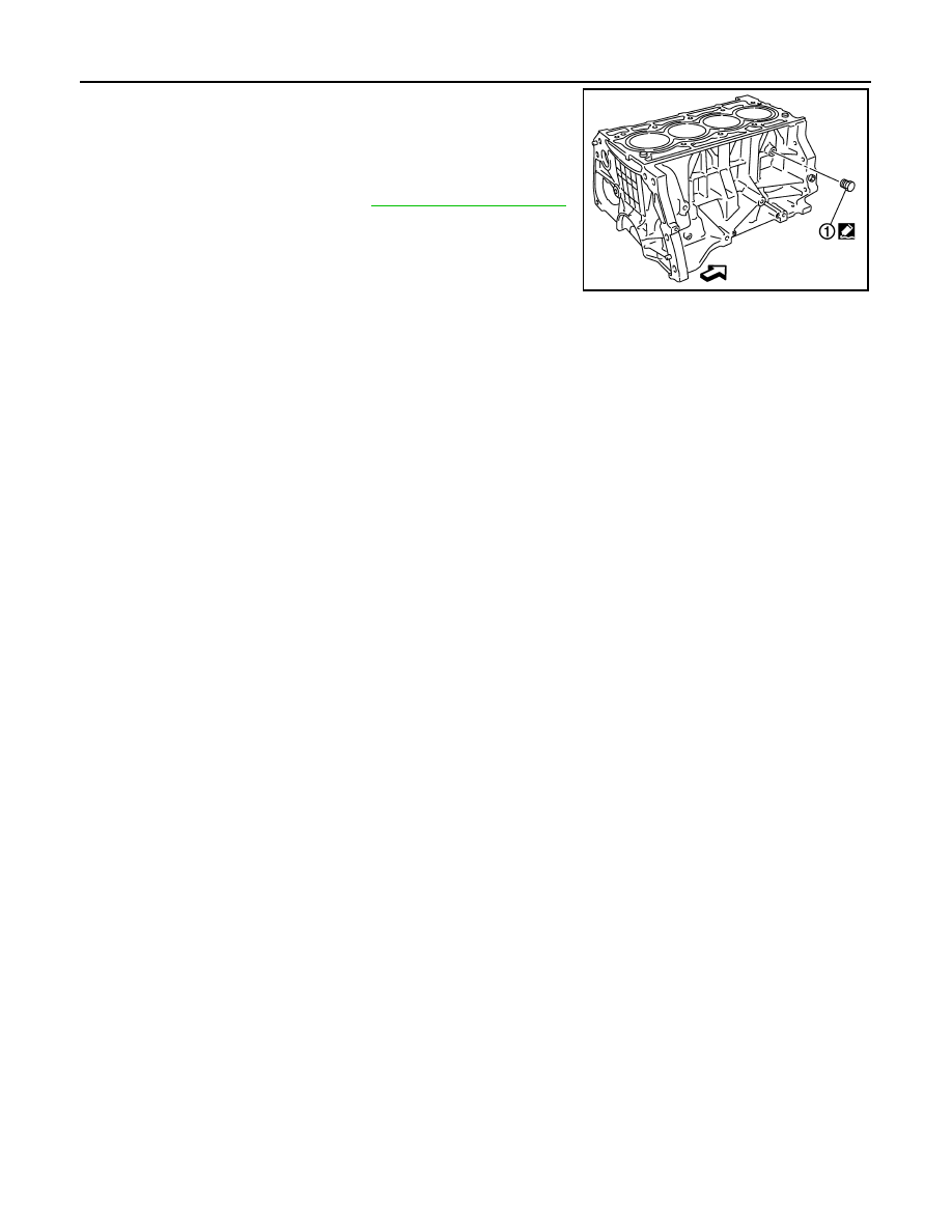
Drain engine coolant by removing water drain plug (1) from
inside of the engine. 

Use Genuine Liquid Gasket or equivalent. 

: Engine front

Tightening torque

: Refer to 

EM-210, "Exploded View"

PBIC3228J

ENGINE UNIT

EM-205

< DISASSEMBLY AND ASSEMBLY >

[MR20DE]

C

D

E

F

G

H

I

J

K

L

M

A

EM

N

P

O

ENGINE UNIT

Disassembly

INFOID:0000000000893996

1.

Remove intake manifold. Refer to 

EM-146, "Exploded View"

.

2.

Remove exhaust manifold. Refer to 

EM-149, "Exploded View"

.

3.

Remove oil pan (lower). Refer to 

EM-152, "Exploded View"

.

4.

Remove oil cooler. Refer to 

LU-18, "Exploded View"

.

5.

Remove ignition coil, spark plug and rocker cover. Refer to 

EM-160, "Exploded View"

.

6.

Remove fuel injector and fuel tube. Refer to 

EM-155, "Exploded View"

.

7.

Remove timing chain. Refer to 

EM-162, "Exploded View"

.

8.

Remove camshaft. Refer to 

EM-173, "Exploded View"

.

9.

Remove water inlet. Refer to 

CO-41, "Exploded View"

.

10. Remove water outlet. Refer to 

CO-44, "Exploded View"

.

11. Remove cylinder head. Refer to 

EM-185, "Exploded View"

.

Assembly

INFOID:0000000000893997

Assembly is the reverse order of disassembly.

EM-206

< DISASSEMBLY AND ASSEMBLY >

[MR20DE]

OIL PAN (UPPER)

OIL PAN (UPPER)

Exploded View

INFOID:0000000000971166

Removal and Installation

INFOID:0000000000971165

1.

Oil level gauge

2.

Oil level gauge guide

3.

Rear oil seal

4.

O-ring

5.

O-ring

6.

Oil pan (upper)

7.

Balancer unit timing chain

8.

Crankshaft sprocket

9.

Balancer unit sprocket

10. Balancer unit timing chain tensioner

11.

Drain plug

12. Drain plug washer

13. Oil pan (lower)

14. Oil filter

15. Connector bolt

16. Oil cooler

17. O-ring

18. Oil level sensor

A.

Refer to 

LU-17

: Oil pan side

Refer to 

GI-4, "Components"

 for symbols in the figure.

PBIC5120J

OIL PAN (UPPER)

EM-207

< DISASSEMBLY AND ASSEMBLY >

[MR20DE]

C

D

E

F

G

H

I

J

K

L

M

A

EM

N

P

O

REMOVAL

1.

Remove oil pan (lower). Refer to 

EM-152, "Exploded View"

.

2.

Remove oil cooler and oil filter. Refer to 

LU-18, "Exploded View"

.

NOTE:
For reference when installing, put a matching mark on oil cooler and oil pan (upper).

3.

Remove front cover, timing chain, balancer unit timing chain and other related parts. Refer to 

EM-162,

"Exploded View"

.

4.

Remove oil level gauge and oil level gauge guide.

5.

Remove oil level sensor, if necessary.

CAUTION:

Never drop or shock oil level sensor.

6.

Remove oil pan (upper) with the following procedure:

a.

Loosen bolts in reverse order as shown in the figure.

b.

Insert a screwdriver shown by the arrow (

) in the figure and

open up a crack between oil pan (upper) and cylinder block.

CAUTION:

A more adhesive liquid gasket is applied compared to previ-
ous types when shipped, so it should not be forced off the
position not specified.

c.

Insert seal cutter [SST: KV10111100] between oil pan (upper) and cylinder block, and slide it by tapping on
the side of the tool with a hammer.

CAUTION:

Be careful not to damage the mating surface.

7.

Remove O-ring between cylinder block and oil pan (upper).

INSTALLATION

1.

Install oil pan (upper) with the following procedure:

a.

Use a scraper (A) to remove old liquid gasket from mating sur-
faces.
• Remove the old liquid gasket from mating surface of cylinder

block.

• Remove old liquid gasket from the bolt holes and threads.

CAUTION:

Never scratch or damage the mating surfaces when clean-
ing off old liquid gasket.

: Engine front

JPBIA0287ZZ

: Engine front

PBIC3948E

PBIC3949E


Content   ..  62  63  64  65   ..