Nissan Qashqai (2007-2010). Manual - part 53
 

  Index      Nissan     Nissan Qashqai - service and repair manual 2007 - 2010 year


Search            copyright infringement  


Content   ..  51  52  53  54   ..


Nissan Qashqai (2007-2010). Manual - part 53


EM-160

< ON-VEHICLE REPAIR >

[MR20DE]

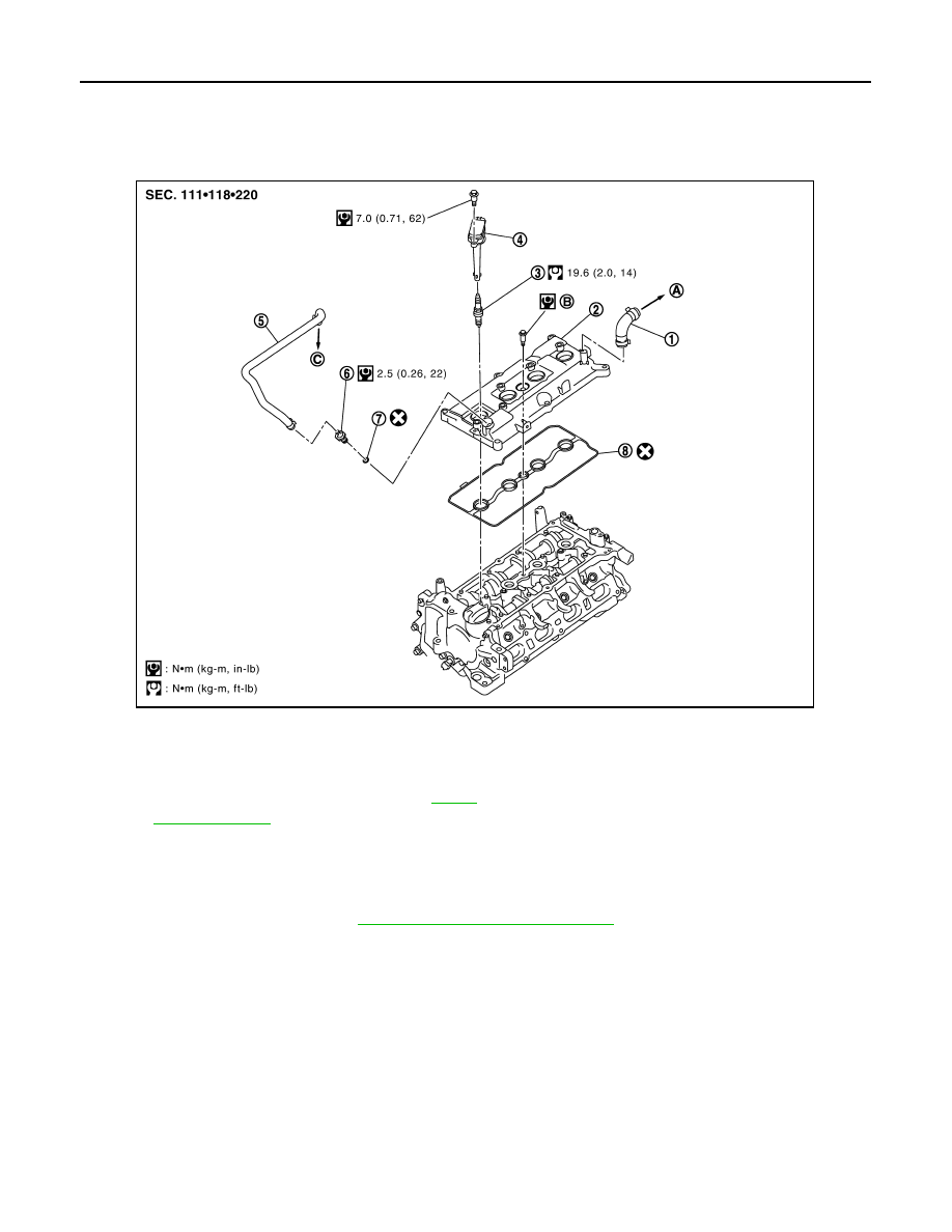
IGNITION COIL , SPRAK PLUG AND ROCKER COVER

IGNITION COIL , SPRAK PLUG AND ROCKER COVER

Exploded View

INFOID:0000000000896389

Removal and Installation

INFOID:0000000000896390

REMOVAL

1.

Remove intake manifold. Refer to 

EM-146, "Removal and Installation"

.   

2.

Remove ignition coil.

CAUTION:

• Handle ignition coil carefully and avoid impacts.
• Never disassemble ignition coil.

3.

Remove rocker cover.

1.

PCV hose

2.

Rocker cover

3.

Spark plug

4.

Ignition coil

5.

PCV hose

6.

PCV valve

7.

O-ring

8.

Gasket

A.

To air duct

B.

Refer to 

EM-160

C.

To intake manifold

Refer to 

GI-4, "Components"

 for symbols in the figure.

PBIC3536J

IGNITION COIL , SPRAK PLUG AND ROCKER COVER

EM-161

< ON-VEHICLE REPAIR >

[MR20DE]

C

D

E

F

G

H

I

J

K

L

M

A

EM

N

P

O

• Loosen bolts in reverse order shown in the figure.

4.

Remove rocker cover gasket from rocker cover.

5.

Use scraper to remove all traces of liquid gasket from cylinder head and front cover.

CAUTION:

Never scratch or damage the mating surface when cleaning off old liquid gasket.

INSTALLATION

1.

Install the rocker cover gasket to rocker cover.

CAUTION:

Make sure the gasket is not dropped.

2.

Install rocker cover.
•  Tighten bolts in two steps separately in numerical order as

shown in the figure.

3.

Install in the reverse order of removal, for the rest of parts. 

: Engine front

PBIC3151J

: Engine front

 1st step

: 1.96 N·m (0.20 kg-m, 17 in-lb)

 2nd step

: 8.33 N·m (0.85 kg-m, 74 in-lb)

PBIC3151J

EM-162

< ON-VEHICLE REPAIR >

[MR20DE]

TIMING CHAIN

TIMING CHAIN

Exploded View

INFOID:0000000000893947

1.

Timing chain slack guide

2.

Timing chain tensioner

3.

Camshaft sprocket (EXH)

4.

Timing chain

5.

Oil filler cap

6.

Front cover

7.

O-ring

8.

Intake valve timing control solenoid 
valve

9.

Crankshaft pulley bolt

10. Crankshaft pulley

11. Front oil seal

12. Drive belt auto-tensioner

13.

Timing chain tension guide
(front cover side)

14. Crankshaft sprocket

15. Balancer unit sprocket

PBIC3538J

TIMING CHAIN

EM-163

< ON-VEHICLE REPAIR >

[MR20DE]

C

D

E

F

G

H

I

J

K

L

M

A

EM

N

P

O

Removal and Installation

INFOID:0000000000893948

REMOVAL

CAUTION:

The rotating direction in the text indicates all directions seen from the engine front.

1.

Remove front wheel (RH). Refer to 

WT-4, "Road Wheel"

.

2.

Remove front fender protector (RH). Refer to 

EXT-21, "Exploded View"

.

3.

Drain engine oil. Refer to 

LU-15, "Draining"

.

CAUTION:

Perform this step when engine is cold.

4.

Remove the following parts.
• Intake manifold: Refer to 

EM-146, "Exploded View"

.

• Rocker cover: Refer to 

EM-160, "Exploded View"

.

• Drive belt: Refer to 

EM-134, "Removal and Installation"

.

5.

Set No. 1 cylinder at TDC on its compression stroke with the following procedure:

a.

Rotate crankshaft pulley (1) clockwise and align TDC mark (no paint) (B) to timing indicator (A) on front
cover. 

b.

At the same time, make sure that the cam noses of the No.1 cyl-
inder are located (

) as shown in the figure.

• If not, rotate crankshaft pulley one revolution (360 degrees)

and align as shown in the figure.

6.

Remove crankshaft pulley with the following procedure:

16. Balancer unit timing chain

17. Camshaft sprocket (INT)

18. Timing chain tension guide

19. O-ring

20. Balancer unit timing chain tensioner

A.

Refer to  

EM-163

B.

Refer to  

EM-163

Refer to 

GI-4, "Components"

 for symbols in the figure.

C

: White paint mark (Not use for service)

PBIC3960E

1

: Camshaft (INT)

2

: Camshaft (EXH)

: Engine front

PBIC3359J


Content   ..  51  52  53  54   ..