Nissan Qashqai (2007-2010). Manual - part 12
 

  Index      Nissan     Nissan Qashqai - service and repair manual 2007 - 2010 year


Search            copyright infringement  


Content   ..  10  11  12  13   ..


Nissan Qashqai (2007-2010). Manual - part 12


CONSULT-III/GST CHECKING SYSTEM

GI-47

< BASIC INSPECTION >

C

D

E

F

G

H

I

J

K

L

M

B

GI

N

O

P

CONSULT-III/GST CHECKING SYSTEM

Description

INFOID:0000000001095984

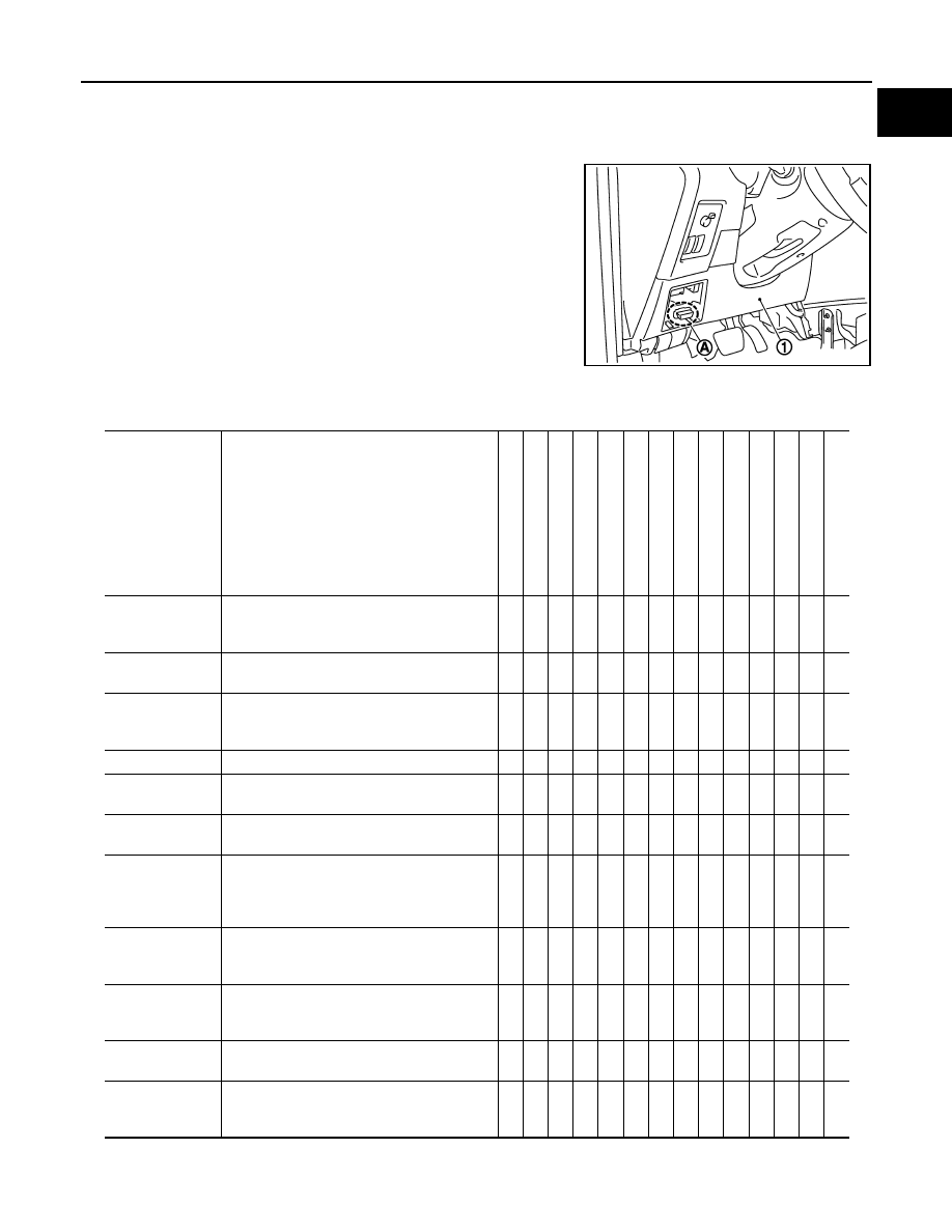
• When CONSULT-III/GST is connected with a data link connector

(A) equipped on the vehicle side, it will communicate with the con-
trol unit equipped in the vehicle and then enable various kinds of
diagnostic tests.

• Refer to CONSULT-III Operation Manual for more information.

CONSULT-III Function and System Application

INFOID:0000000001095985

1

: Instrument driver lower panel

JPAIA0048ZZ

Diagnostic test 

mode

Function

ENGINE

TRANSMISSION

AIR BAG

METER/M

&

A

BCM

ABS

ABS (I

ncluding 

ESP)

IP

DM E/

R

ALL MODE A

W

D/4WD

HEAD LAMP LE

VELI

Z

ER

MUL

T

I A

V

REA

R

 VIEW CAMERA

EPS

INT

E

LL

IGENT KE

Y

Work support

This mode enables a technician to adjust 
some devices faster and more accurately by 
following the indications on CONSULT-III.

x

x

-

-

x

-

x

-

-

x

-

x

-

x

Self-diagnostic 
results

Self-diagnostic results can be read and 
erased quickly.

x

x

x

x

x

x

x

x

x

x

x

-

x

x

Trouble diagnos-
tic record

Current self-diagnostic results and all trouble 
diagnostic records previously stored can be 
read.

-

-

x

-

-

-

-

-

-

-

-

-

-

-

Data  monitor

Input/Output  data  in  the  ECU  can  be  read.

x

x

-

x

x

x

x

x

x

x

x

x

x

x

CAN diagnosis

The condition of CAN communication line can 
be indicated by a topology.

x

x

-

x

x

x

x

x

x

-

x

-

x

x

CAN diagnosis 
support monitor

The condition of CAN communication line can 
be read.

x

x

-

x

x

x

x

x

x

-

x

-

x

x

Active test

Diagnostic Test Mode in which CONSULT-III 
drives some actuators apart from the ECUs 
and also shifts some parameters in a speci-
fied range.

x

-

-

-

x

x

x

x

x

x

-

-

-

x

DTC & SRT con-
firmation

The results of SRT (System Readiness Test) 
and the self-diagnosis status/result can be 
confirmed.

x*

-

-

-

-

-

-

-

-

-

-

-

-

-

DTC work sup-
port

This mode enables a technician to monitor 
the status/results of self-diagnosis performed 
by the ECU.

-

-

-

-

-

-

-

-

-

-

-

-

-

-

ECU (ECM/TCM) 
part number

ECU  (ECM/TCM)  part  number  can  be  read.

x

x

-

-

x

x

x

x

x

-

x

x

x

x

ECU discriminat-
ed No.

Classification number of a replacement ECU 
can be read to prevent an incorrect ECU from 
being installed.

-

-

x

-

-

-

-

-

-

x

-

-

-

-

GI-48

< BASIC INSPECTION >

CONSULT-III/GST CHECKING SYSTEM

x: Applicable

* : Petrol engine models

CONSULT-III Data Link Connector (DLC) Circuit

INFOID:0000000001095986

INSPECTION PROCEDURE

If the CONSULT-III cannot diagnose the system properly, check the following items.

NOTE:
The DDL1 and DDL2 circuits from DLC pins 12, 13, 14 and 15 may be connected to more than one system. A
short in a DDL circuit connected to a control unit in one system may affect CONSULT-III access to other sys-
tems.

Function test

This mode can show results of self-diagnosis 
of ECU with either 'OK' or 'NG'. For engines, 
more practical tests regarding sensors/
switches and/or actuators are available.

x*

x

x

-

-

x

x

-

-

-

-

-

-

-

Configration

Function to READ/WRITE vehicle configura-
tion on BCM.

-

-

-

-

x

-

-

-

-

-

-

-

-

-

AV COMM moni-
tor

The condition of AV communication can be in-
dicated.

-

-

-

-

-

-

-

-

-

-

x

-

-

-

CALIB data

Characteristic information for TCM and CVT 
assembly can be read.

-

x

-

-

-

-

-

-

-

-

-

-

-

-

Diagnostic test 

mode

Function

ENGINE

T

R

ANSMI

SSION

AI

R BAG

METER/

M&A

BCM

AB

S

A

BS (Incl

u

ding ES

P)

IPDM

 E/R

ALL MO

DE 

A

W

D/4WD

HEAD LA

MP 

LEVE

LIZE

R

MUL

T

I A

V

REAR VI

EW CAMERA

EP

S

INTELLI

G

E

N

T

 KEY

Symptom

Check item

CONSULT-III cannot access 
any system.

• CONSULT-III DLC power supply circuit (Terminal 8) and ground circuit (Terminal 4) 

CONSULT-III cannot access in-
dividual system. (Other sys-
tems can be accessed.)

• Power supply and ground circuit for the control unit of the system (For detailed circuit, refer to wiring 

diagram for each system.)

• Open or short circuit between the system and CONSULT-III DLC (For detailed circuit, refer to wiring 

diagram for each system.)

• Open or short circuit CAN communication line. Refer to 

LAN-46, "Trouble Diagnosis Flow Chart"

.

CONSULT-III/GST CHECKING SYSTEM

GI-49

< BASIC INSPECTION >

C

D

E

F

G

H

I

J

K

L

M

B

GI

N

O

P

Wiring Diagram - CONSULT-III/GST CHECKING SYSTEM -

INFOID:0000000001095987

JCAWA0016GB

GI-50

< BASIC INSPECTION >

CONSULT-III/GST CHECKING SYSTEM

JCAWA0017GB


Content   ..  10  11  12  13   ..