Mitsubishi L200 (2018 year). Manual - part 24
 

  Index      Mitsubishi     Mitsubishi L200 - service manual 2018 year in english


Search            


Content   ..  22  23  24  25   ..


Mitsubishi L200 (2018 year). Manual - part 24


2. Turn the bulb socket anticlockwise to re-

move  it.  And  remove  the  bulb  from  the
socket by turning it anticlockwise while
pressing in.

3. To install the bulb, perform the removal

steps in reverse.

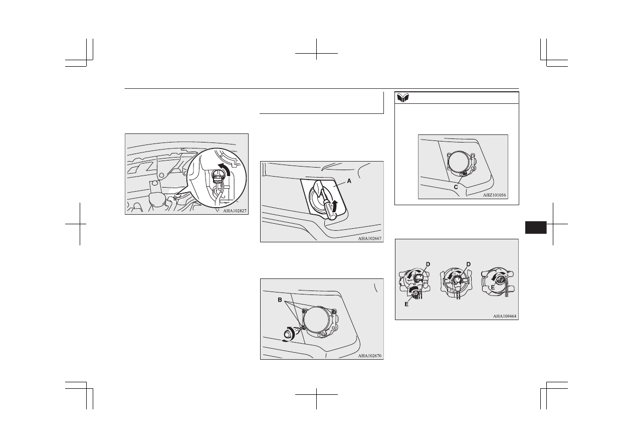
Front fog lamps* / Daytime

running lamps*

E01004003469

1. Insert a straight blade (or minus) screw-

driver with a cloth over its tip at the edge
of  the  cover  (A)  and  pry  gently  to  re-
move the cover.

2. Remove  the  3  screws  (B)  and  remove

the lamp unit.

NOTE

l

When  unfastening  the  screws  of  the  fog
lamp, be careful not to mistakenly move the
beam position adjustment screw (C).

3. Turn the socket anticlockwise to remove

it.

Type 1

Type 2

Type 3

D- Front fog lamp
E- Daytime running lamp

Replacement of lamp bulbs

10-27

OKTE18E1

Maintenance

10

4. While holding down the tab (F), pull out

the bulb (G).

Front fog lamp

Daytime running lamp

5. To install the bulb, perform the removal

steps in reverse.

Rear combination lamps

E01004202884

1. Open the rear gate.

(Refer to “Rear gate” on page 3-20.)

2. Remove  the  screws  (A)  that  hold  the

lamp unit.

3. Move  the  lamp  unit  towards  the  rear  of

the vehicle and remove the clips (B).

4. Remove  each  socket  and  bulb  assembly

by turning it anticlockwise.

C-

Tail and stop lamp
Remove the bulb from the sock-
et  by  turning  it  anticlockwise
while pressing in.

D-

Rear turn-signal lamp
Remove  the  bulb  by  pulling  it
out.

E-

Rear  fog  lamp  (driver’s  side)*/
Reversing lamp
Remove  the  bulb  by  pulling  it
out.

5. To install the bulb, perform the removal

steps in reverse.

Replacement of lamp bulbs

10-28

OKTE18E1

Maintenance

10

NOTE

l

When mounting the lamp unit, align the pins
(F)  and  clip  (G)  on  the  lamp  unit  with  the
holes (H) in the body.

Licence plate lamps

E01004602224

1. Insert a straight blade (or minus) screw-

driver  into  the  lamp  assembly  and  pry
gently to remove it.

NOTE

l

Wrap  a  piece  of  cloth  around  the  tip  of  the
screwdriver in order to avoid scratching the
lens and the body.

2. Remove  the  socket  and  bulb  assembly

together by turning it anticlockwise, and
then remove the bulb by pulling it out.

3. To install the bulb, perform the removal

steps in reverse.

Replacement of lamp bulbs

10-29

OKTE18E1

Maintenance

10

NOTE

l

When mounting the lamp unit, put the hook
(A) on the right side of the lamp unit into the
body first.

Front room & map lamps*

E01010501074

1. Insert a straight blade (or minus) screw-

driver into the notch of the lens and pry
gently to remove it.
Remove the bulb from the lamp holder.

NOTE

l

Wrap  a  piece  of  cloth  around  the  tip  of  the
screwdriver in order to avoid scratching the
lens.

2. To install the bulb, perform the removal

steps in reverse.

NOTE

l

When installing the lens, align the 2 tabs on
the lens with the holes on the vehicle side.

Rear room lamp

E01004901464

Type 1

1. Insert a straight blade (or minus) screw-

driver into the notch of the lens and pry

gently  to  remove  it.  Remove  the  bulb
from the lamp holder.

NOTE

l

Wrap  a  piece  of  cloth  around  the  tip  of  the
screwdriver in order to avoid scratching the
lens.

2. To install the bulb, perform the removal

steps in reverse.

NOTE

l

When installing the lens, align the 2 tabs on
the lens with the holes on the vehicle side.

Replacement of lamp bulbs

10-30

OKTE18E1

Maintenance

10

NOTE

l

When installing the lens, fit the two tabs on
one side of the lens into the holes on the ve-
hicle  side  before  fitting  the  two  tabs  on  the
opposite side of the lens into the holes on the
vehicle side.

Type 2

1. Insert a straight blade (or minus) screw-

driver into the notch of the lens and pry

gently  to  remove  it.  Remove  the  bulb
from the lamp holder.

NOTE

l

Wrap  a  piece  of  cloth  around  the  tip  of  the
screwdriver in order to avoid scratching the
lens.

2. To install the bulb, perform the removal

steps in reverse.

NOTE

l

When installing the lens, fit the two tabs on
one side of the lens into the holes on the ve-
hicle  side  before  fitting  the  two  tabs  on  the
opposite side of the lens into the holes on the
vehicle side.

Glove box lamp

E01006101516

Have  the  glove  box  lamp  bulb  replaced  at  a
MITSUBISHI MOTORS Authorized Service
Point.

Masking the headlamps

E01011601085

When  entering  a  country  in  which  vehicles
are driven on the opposite side of the road to
the  country  in  which  your  vehicles  is  sup-
plied, necessary measures have to be taken to
avoid dazzling oncoming traffic.

Masking the headlamps

10-31

OKTE18E1

Maintenance

10

High intensity discharge head-

lamp type

Do not need any adjustment.

Halogen headlamp type

Mask  the  headlamps  according  to  the  next
procedure.

1. Turn the headlamp off and wait until the

headlamps got cold.

2. According  to  the  illustrations,  prepare

the sticker (A) to stick the headlamp sur-
face of right and left.

NOTE

l

Use  a  sticker  with  a  light  blocking  effect
enough.
Using  of  a  sticker  without  a  light  blocking
effect will not acquire a blocking effect.

3. Seeing from the headlamp front, position

(C)  of  the  sticker  and  the  central  mark
(B)  of  the  headlamp  and  stick  a  sticker
along the vertical dotted line.

NOTE

l

Align the vertical dotted line with the line of
the reflector in the headlamp.

LHD

Left lens

Right lens

115mm

105mm

37mm

50mm

RHD

Left lens

Right lens

105mm

37mm

50mm

115mm

Masking the headlamps

10-32

OKTE18E1

Maintenance

10

Vehicle labeling

E01100105005

Vehicle Identification Number:

(VIN)

The vehicle identification number is stamped
as shown in the illustration.

Vehicle identification number

plate (RHD vehicles only)

The vehicle identification number is stamped
on the plate riveted to the left front corner of
the vehicle body. It is visible from outside of
the vehicle through the windscreen.

Vehicle information code plate

E01102200034

The vehicle information code plate is located
as shown in the illustration.

The  plate  shows  model  code,  engine  model,
transmission  model  and  body  colour  code,
etc.
Please  use  this  number  when  ordering  re-
placement parts.

Vehicle labeling

11-02

OKTE18E1

Specifications

11

1- Model code
2- Engine model code
3- Transmission model code
4- Final gear ratio
5- Body colour code
6- Interior code
7- Option code

Engine model/number

E01102500125

The  engine  model  and  number  are  stamped
on the engine cylinder block as shown in the
illustrations.

Vehicle labeling

11-03

OKTE18E1

Specifications

11

Vehicle dimensions

E01100204692

Single cab

Vehicle dimensions

11-04

OKTE18E1

Specifications

11

Single cab

1

Front track

1,520 mm

2

Overall width

1,785 mm

3

Front overhang

865 mm

4

Wheel base

3,000 mm

5 Rear overhang

Without rear bumper

1,215 mm

With rear bumper

1,295 mm

6

Overall length

Without rear bumper

5,080 mm

With rear bumper

5,160 mm

7

Ground clearance (unladen)

200 mm

8

Overall height (unladen)

1,780 mm

9

Rear track

1,515 mm

10 Cargo bed length

2,265 mm

11 Cargo bed width

1,470 mm

12 Cargo bed height

845 mm

Minimum turning radius

Body

6.3 m

Wheel

5.9 m

Vehicle dimensions

11-05

OKTE18E1

Specifications

11

Club cab

Vehicle dimensions

11-06

OKTE18E1

Specifications

11

Club cab

1

Front track

1,520 mm

2

Overall width

1,785 mm, 1,815 mm

*

3

Front overhang

865 mm

4

Wheel base

3,000 mm

5 Rear overhang

Without rear bumper

1,330 mm

With rear bumper

1,410 mm

6

Overall length

Without rear bumper

5,195 mm

With rear bumper

5,275 mm

7

Ground clearance (unladen)

200 mm, 205 mm

*

8

Overall height (unladen)

1,775 mm, 1,780 mm

*

9

Rear track

1,515 mm

10 Cargo bed length

1,850 mm

11 Cargo bed width

1,470 mm

12 Cargo bed height

845 mm, 850 mm

*

*

: Vehicles with wide fender

NOTE

l

The vehicle overall length and height may vary depending on the equipment installed.

Minimum turning radius

Body

6.3 m

Vehicle dimensions

11-07

OKTE18E1

Specifications

11

Wheel

5.9 m

Double cab

Vehicle dimensions

11-08

OKTE18E1

Specifications

11

Double cab

1

Front track

1,520 mm

2

Overall width

1,785 mm, 1,815 mm

*

3

Front overhang

865 mm

4

Wheel base

3,000 mm

5 Rear overhang

Without rear bumper

1,340 mm

With rear bumper

1,420 mm

6

Overall length

Without rear bumper

5,205 mm

With rear bumper

5,285 mm

7

Ground clearance (unladen)

200 mm, 205 mm

*

8

Overall height (unladen)

1,775 mm, 1,780 mm

*

9

Rear track

1,515 mm

10 Cargo bed length

1,520 mm

11 Cargo bed width

1,470 mm

12 Cargo bed height

845 mm, 850 mm

*

*

: Vehicles with wide fender

Minimum turning radius

Body

6.3 m

Wheel

5.9 m


Vehicle dimensions

11-09

OKTE18E1

Specifications

11

Vehicle performance

E01100304071

Single cab

Maximum speed

169 km/h (105 mph)

Club cab

Item

Vehicles without wide fender

Vehicles with wide fender

Maximum speed

169 km/h (105 mph)

179 km/h (111 mph)

Double cab

Item

Vehicles without wide

fender

Vehicles with wide fender

M/T

A/T

Maximum speed

169 km/h (105 mph)

174 km/h, 179 km/h

*

173 km/h, 177 km/h

*

*

: Vehicles with high power engine


Vehicle weight

E01100408650

Single cab

Kerb weight

Without optional parts

1,790 kg

With full optional parts

1,835 kg

Maximum gross vehicle weight

2,850 kg

Maximum axle weight

Front

1,260 kg

Vehicle performance

11-10

OKTE18E1

Specifications

11


Content   ..  22  23  24  25   ..