Mitsubishi L200 (2018 year). Manual - part 21
 

  Index      Mitsubishi     Mitsubishi L200 - service manual 2018 year in english


Search            


Content   ..  19  20  21  22   ..


Mitsubishi L200 (2018 year). Manual - part 21


Stop the engine immediately and contact
a  MITSUBISHI  MOTORS  Authorized
Service Point for assistance.

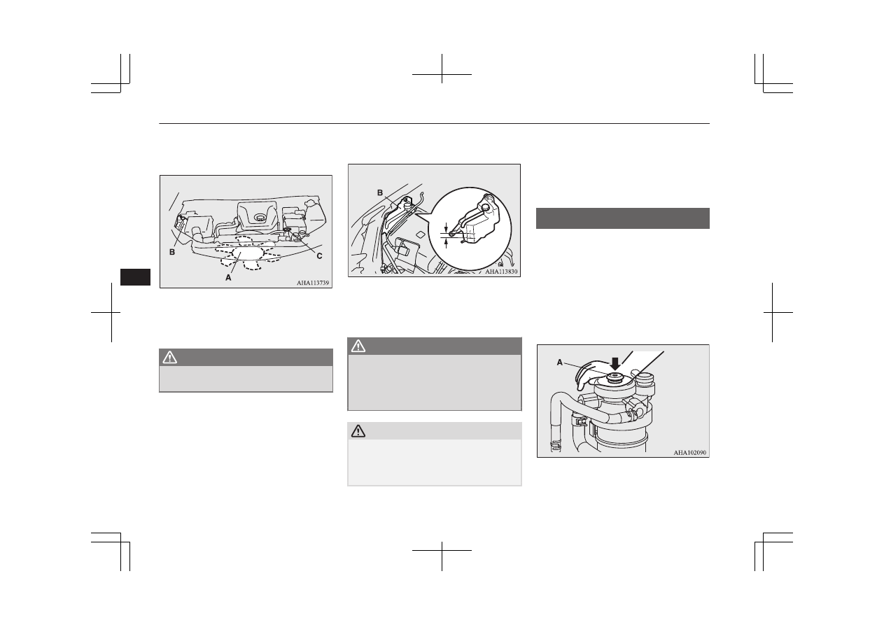
A- Cooling fan
B- Reserve tank
C- Radiator cap

WARNING

l

Be careful not to get your hands or clothes
caught in the cooling fan.

4. Check  the  coolant  level  in  the  reserve

tank (B).

FULL

LOW

5. Add  coolant  to  the  radiator  and/or  re-

serve  tank  if  necessary  (refer  to  the
“Maintenance” section).

WARNING

l

Make  sure  that  the  engine  has  cooled
down  before  removing  the  radiator  cap
(C),  because  hot  steam  or  boiling  water
otherwise  will  gush  from  the  filler  port
and may scald you.

CAUTION

l

Do not add coolant while the engine is hot.
Suddenly adding cold coolant could damage
the  engine.  Wait  for  the  engine  to  cool
down, then add coolant a little at a time.

6. Examine  the  radiator  hoses  for  coolant

leakage  and  the  drive  belt  for  looseness
or damage.
If there is anything wrong with the cool-
ing system or drive belt, we recommend
you to have it checked and repaired.

Bleeding the fuel system

E00800701423

The fuel system should be bled to remove air
as  described  below  if  the  fuel  supply  is  ex-
hausted during travel.
Pump  the  hand  pump  (A)  at  the  top  of  the
fuel filter until the hand pump becomes stiff.
Then try again to start the engine.
If the engine does not start, repeat the process
above.

Bleeding the fuel system

8-10

OKTE18E1

For emergencies

8

CAUTION

l

Do not smoke or have any other open flame
near the vehicle while bleeding the fuel sys-
tem.

l

Be sure to carefully clean away any spilt fuel
which could ignite and cause a fire.

Removal of water from the
fuel filter

E00800801525

If the fuel filter indication lamp in the instru-
ment panel illuminates during driving, it indi-
cates  that  water  has  accumulated  in  the  fuel
filter. If this occurs, remove the water as de-
scribed below.

1. Loosen the drain plug (A) of the fuel fil-

ter.

2. Operate the hand pump (B) slowly 6 or 7

times  in  order  to  force  the  water  out
through the drain plug (A).

3. Tighten  the  drain  plug  (A)  when  water

no longer comes out.

4. Bleed the air in the fuel system.

(Refer to “Bleeding the fuel system” on
page 8-10.)

5. Check to be sure that the fuel filter indi-

cation  lamp  illuminates  when  the  igni-
tion switch is turned to “ON” or the op-
eration  mode  is  put  in  ON,  and  that  it
goes off when the engine is started. If in
doubt,  we  recommend  you  to  consult  a
specialist for necessary information.

CAUTION

l

Do not smoke or have any other open flame
near the vehicle while bleeding the fuel sys-
tem.

CAUTION

l

Be  sure  to  carefully  clean  away  any  water
drained out because any fuel mixed with the
water could ignite and cause a fire.

Tools, jack and jack handle

E00800902695

Storage

The  storage  location  of  the  tools,  jack  and
jack handle should be remembered in case of
an emergency.

Single cab

Type 1

A- Tool (wheel nut wrench)
B- Jack handle

Removal of water from the fuel filter

8-11

OKTE18E1

For emergencies

8

C- Jack

Type 2

A- Tools
B- Jack handle
C- Jack

Club cab

A- Tools
B- Jack
C- Jack handle

Double cab

Type 1

A- Tool (wheel nut wrench)
B- Jack handle
C- Jack

Type 2

A- Tools
B- Jack handle
C- Jack

Tools

E00801902142

Type 1

Club cab

Single cab/Double cab

Single cab/Double cab

1- Wheel nut wrench

Club cab

1- Tool bag
2- Wheel nut wrench

Tools, jack and jack handle

8-12

OKTE18E1

For emergencies

8

Type 2

1- Tool bag
2- Wheel nut wrench
3- Plier
4- Driver
5- Spanner

Jack

E00802001765

The  jack  is  used  only  for  the  purpose  of
changing a tyre when a tyre is punctured.

NOTE

l

The jack is maintenance-free.

l

The jack is in conformity with EC law as ap-
proximated  by  the  Machinery  Directive
2006/42/EC.

NOTE

l

The EC declaration of conformity is attached
to  the  section  “Declaration  of  Conformity”
in the end of this owner’s manual.

The  business  name,  full  address  of  the
manufacturer and of his authorized repre-
sentative  and  the  designation  of  the  jack
are  described  in  the  EC  declaration  of
conformity.

Removing and storing the

tools, jack and jack handle

E00802301481

Single cab

The  tools,  jack,  and  jack  handle  are  located
behind the seat.

1. Tip the seatback forward.

(Refer to “Front seats” on page 4-02).

2. <Type 1>

Remove the wheel nut wrench (A) from
the holder (B), and take out the wrench.
<Type 2>

Remove the securing band (C), and then
take out the tools (D).

3. Remove  the  securing  nut  (E),  and  then

take out the jack (F).

Tools, jack and jack handle

8-13

OKTE18E1

For emergencies

8

4. Remove  the  jack  handle  (G)  from  the

holder (H), and take out the handle.

5. Reverse  the  removing  procedure  when

storing the tools, jack and jack handle.

NOTE

l

When  stowing  the  jack  handle,  align  the
black-marked part (I) of the jack handle with
the holder (H).

Club cab

The  tools  are  stored  under  the  floor  on  the
left-hand side of the rear seat.
The  jack,  and  jack  handle  are  stored  under
the  floor  on  the  right-hand  side  of  the  rear
seat.

1. Raise the seat cushion. Refer to “Folding

up the seat cushion (Club cab)*” on page
4-04.
Open the rear door. Refer to “To open or
close the rear door (Club cab)” on page
3-16.

2. Open the lid.

3. Remove the securing band (A), and then

take  out  the  tools  (B)  on  the  left-hand
side.

Tools, jack and jack handle

8-14

OKTE18E1

For emergencies

8

4. Remove  the  securing  nut  (C),  and  then

take  out  the  jack  (D)  on  the  right-hand
side.

5. Remove  the  jack  handle  (E)  from  the

holder  (F),  and  then  take  out  the  jack
handle on the right-hand side.

6. Reverse  the  removing  procedure  when

storing the tools, jack and jack handle.

NOTE

l

When stowing the jack handle, align the col-
oured  marking  on  the  jack  handle  with  that
on the holder, and fit the jack in the holder.

Double cab

The  tools,  jack,  and  jack  handle  are  located
behind the rear seat.

1. Tip the seatback of the rear seat forward.

(Refer to “Folding the seatback forward
(Double cab)” on page 4-04.)

2. <Type 1>

Remove the wheel nut wrench (A) from
the holder (B), and take out the wrench.
<Type 2>
Remove the securing band (C), and then
take out the tools (D).

3. Remove  the  securing  nut  (E),  and  then

take out the jack (F).

4. Remove  the  jack  handle  (G)  from  the

holder (H), and take out the handle.

5. Reverse  the  removing  procedure  when

storing the tools, jack and jack handle.

Tools, jack and jack handle

8-15

OKTE18E1

For emergencies

8

NOTE

l

When  stowing  the  jack  handle,  align  the
black-marked part (I) of the jack handle with
the holder (H).

To use the jack handle (Club

cab)

E00802401189

1. While  pressing  the  snap  pin  (A)  on  the

handle  that  has  a  black  marking,  with-
draw and remove the inner handle (B).

2. Reverse the inner handle (B) then, while

pressing  the  snap  pin  (C),  insert  it  into
the outer handle (D) until it is locked by
the snap pin as illustrated.

3. While  pressing  the  snap  pin  (F)  on  the

assembled  handle  (E),  insert  the  white-
marked  handle  (G)  until  it  is  locked  by
the snap pin as illustrated.

Tools, jack and jack handle

8-16

OKTE18E1

For emergencies

8

How to change a tyre

E00801204051

Before  changing  a  tyre,  first  stop  your  vehi-
cle in a safe, flat location.

1. Park  the  vehicle  on  level  and  stable

ground, free of loose pebbles, etc.

2. Set the parking brake firmly.
3. On  vehicles  with  manual  transmission,

turn  the  ignition  switch  to  the  “LOCK”
position  or  put  the  operation  mode  in
OFF, and move the gearshift lever to the
“R” (Reverse) position.
On  vehicles  with  automatic  transmis-
sion,  move  the  selector  lever  to  the  “P”
(PARK)  position,  and  turn  the  ignition
switch  to  the  “LOCK”  position  or  put
the operation mode in OFF.

4. Turn on the hazard warning flashers and

set up a warning triangle, flashing signal
lamp, etc., at an adequate distance from
the vehicle, and have all your passengers
leave the vehicle.

5. To  prevent  the  vehicle  from  rolling

when  jacking  up  the  vehicle,  place
chocks  or  blocks  (A)  at  the  tyre  that  is
diagonally  opposite  from  the  tyre  (B)
you are changing.

WARNING

l

Be  sure  to  apply  chocks  or  blocks  to  the
correct  tyre  when  jacking  up  the  vehicle.
If  the  vehicle  moves  while  jacked  up,  the
jack  could  slip  out  of  position,  leading  to
an accident.

NOTE

l

The chocks shown in the illustration do not
come  with  your  vehicle.  It  is  recommended
that  you  keep  one  in  the  vehicle  for  use  if
needed.

l

If chocks are not available, use stones or any
other  objects  that  are  large  enough  to  hold
the wheel in position.

6. Get the jack, jack handle and wheel nut

wrench ready.
Refer  to  “Tools,  jack  and  jack  handle”
on page 8-11.

Spare wheel information

E00803601801

The  spare  wheel  is  stored  under  the  floor  of
the cargo bed.
Check  the  air  pressure  of  the  spare  tyre  fre-
quently  and  make  sure  it  is  ready  for  emer-
gency use at any time.
 
Maintaining  the  spare  wheel  at  the  highest
specified  air  pressure  will  ensure  that  it  can
always  be  used  under  any  conditions  (city/
high-speed  driving,  varying  load  weight,
etc.).

CAUTION

l

The pressure should be periodically checked
and  maintained  at  the  specified  pressure
while the tyre is stowed.
Driving  with  an  insufficient  tyre  pressure
can  lead  to  an  accident.  If  you  have  no
choice but to drive with an insufficient tyre
pressure,  keep  your  speed  down  and  inflate
the  tyre  to  the  correct  pressure  as  soon  as
possible. (Refer to “Tyre inflation pressures”
on page 10-12.)

To remove the spare wheel

E00803501594

1. Set the jack handle. (Club cab)

(Refer to “To use the jack handle (Club
cab)” on page 8-16.)

How to change a tyre

8-17

OKTE18E1

For emergencies

8

2. Insert the jack handle (A) in the hole (B)

below the rear gate.

3. Securely  insert  the  pin  (C)  on  the  jack

handle  into  the  holder  (D)  of  the  spare
wheel carrier.

4. Insert the wheel nut wrench (E) through

the end of the jack handle hole (F), and
then  turn  it  anticlockwise  to  lower  the

spare  wheel  completely  to  the  ground
and to slack the chain.

CAUTION

l

When removing the spare wheel, please ob-
serve the followings.
If you do not follow them, it could result in
break the spare wheel carrier.

Do  not  use  a  power  tool.  Use  the  wheel
nut wrench stowed on the vehicle.

Do not apply a force of 400 N or more at
the end of the wheel nut wrench.

5. Remove  the  hanger  disc  (G)  from  the

spare wheel.

NOTE

l

Put  the  spare  wheel  under  the  vehicle  body
near  the  flat  tyre.  This  makes  it  safer  if  the
jack slips out of position.

How to change a tyre

8-18

OKTE18E1

For emergencies

8

To change a tyre

E00803202237

1. Loosen  the  wheel  nuts  a  quarter  turn

with  the  wheel  nut  wrench.  Do  not  re-
move the wheel nuts yet.

2. Place  the  jack  under  one  of  the  jacking

points shown in the illustration. Use the
jacking point closest to the tyre you wish
to change.

A- Front jacking point

B- Rear jacking point

WARNING

l

Set  the  jack  only  at  the  positions  shown
here. If the jack is set at a wrong position,
it  could  dent  your  vehicle  or  the  jack
might fall over and cause personal injury.

l

Do not use the jack on a tilted or soft sur-
face.  Otherwise,  the  jack  might  slip  and
cause  personal  injury.  Always  use  the
jack on a flat, hard surface. Before setting
the jack, make sure there are no sand or
pebbles under the jack base.

NOTE

l

When jacking up the rear of the vehicle, turn
the tip of the jack so that the grooved portion
(C) properly meets the designated point.

3. Using  the  jack  handle,  turn  the  release

valve (D) clockwise until it stops.

How to change a tyre

8-19

OKTE18E1

For emergencies

8

4. Insert  the  jack  handle  in  the  bracket  of

the  jack  and  hook  the  notch  (E)  on  the
jack  handle  end  to  the  claw  (F)  of  the
bracket.

5. Move  the  jack  handle  up  and  down  to

raise  the  ram  until  just  before  the  jack
contacts the jacking point of the vehicle.
Ensure  that  the  jack  will  properly  con-
tact the vehicle jacking point.
Move  the  jack  handle  up  and  down  to
raise the vehicle.

NOTE

l

This jack is a 2 stage expansion type.

WARNING

l

Stop jacking up the vehicle as soon as the
tyre is raised off the ground. It is danger-
ous to raise the vehicle any higher.

WARNING

l

Do not get under your vehicle while using
the jack.

l

Do not bump the raised vehicle or leave it
sitting  on  the  jack  for  a  long  time.  Both
are very dangerous.

l

Do  not  use  a  jack  except  the  one  that
came with your vehicle.

l

The jack should not be used for any pur-
pose other than to change a tyre.

l

No one should be in your vehicle when us-
ing the jack.

l

Do not start or run the engine while your
vehicle is on the jack.

l

Do  not  turn  the  raised  wheel.  The  tyres
still  on  the  ground  could  turn  and  make
your vehicle fall off the jack.

6. Remove  the  wheel  nuts  with  the  wheel

nut wrench, then take the wheel off.

CAUTION

l

Handle  the  wheel  carefully  when  changing
the  tyre,  to  avoid  scratching  the  wheel  sur-
face.

7. Clean out any mud, etc. on the hub sur-

face (G), hub bolts (H) or in the installa-
tion  holes  (I)  in  the  wheel,  and  then
mount the spare wheel.

WARNING

l

Mount  the  spare  wheel  with  the  valve
stem  (J)  facing  outboard.  If  you  cannot
see  the  valve  stem  (J),  you  have  installed
the wheel backwards.
Operating  the  vehicle  with  the  spare
wheel installed backwards can cause vehi-
cle damage and result in an accident.

How to change a tyre

8-20

OKTE18E1

For emergencies

8

8. Turn  the  wheel  nuts  clockwise  by  hand

to initially tighten them.
[Type 1: On vehicles with steel wheels]
Temporarily  tighten  the  wheel  nuts  by
hand until the tapered parts of the wheel
nuts make light contact with the seats of
the  wheel  holes  and  the  wheel  is  not
loose.
[Type  2:  On  vehicles  with  aluminium
wheels]
Temporarily  tighten  the  wheel  nuts  by
hand  until  the  flange  parts  of  the  wheel
nuts  make  light  contact  with  the  wheel
and the wheel is not loose.

Type 1

Type 2

NOTE

l

Flange  nuts  can  be  temporarily  used  on  the
steel  spare  wheel  as  shown  in  the  illustra-
tion, but return to the original wheel and tyre
as soon as possible.

CAUTION

l

Never  apply  oil  to  either  the  wheel  bolts  or
the nuts, or they will tighten too much.

NOTE

l

If  all  4  aluminium  wheels  are  changed  to
steel wheels. e. g. when fitting winter tyres,
use tapered nuts.

9. Put  the  notch  (K)  provided  on  the  jack

handle end on the valve (L) of the jack.
Using  the  jack  handle,  turn  the  release
valve  anticlockwise  slowly  to  lower  the
vehicle until the tyre touches the ground.

WARNING

l

Be sure to open the release valve slowly. If
it is opened quickly, the vehicle will drop
abruptly  and  the  jack  may  come  out  of
position, causing a serious accident.

10. Tighten  the  nuts  crisscross  in  2  or  3

steps  until  each  nut  has  been  tightened
securely.

How to change a tyre

8-21

OKTE18E1

For emergencies

8


Tightening torque

Steel wheel: 137 to 157 N•m
Aluminium wheel: 118 to 137 N•m

(Achieved  by  applying  a  force  at  the
end of the wheel nut wrench supplied
with the vehicle.
Steel wheel: 510 to 580 N
Aluminium wheel: 440 to 500 N)

CAUTION

l

Never use your foot or a pipe extension for
extra  force  in  the  wheel  nut  wrench.  If  you
do so, you will tighten the nut too much.

11. Lower  the  jack  all  the  way  and  remove

it.

CAUTION

l

If the release valve is loosened too much (2
or more turns) in the anticlockwise direction,
the  jack’s  oil  will  leak  and  the  jack  cannot
be used.

l

Close  the  release  valve  slowly  when  lower-
ing  the  vehicle,  or  the  valve  may  be  dam-
aged.

NOTE

l

Occasionally when the vehicle is jacked up,
the  grooved  portion  of  the  designated  point
will not come off. When this happens, rock
the vehicle to lower the ram.

l

If the jack is difficult to remove by hand, in-
sert the jack handle (M) into the bracket (N).
Then using the handle, remove the jack.

AHZ101131

12. Press  the  piston  down  all  the  way,  and

turn the release valve clockwise as far as
possible.

13. Check  your  tyre  inflation  pressure.  The

correct pressures are shown on the door
label. See the illustration.

CAUTION

l

The  tyre  pressure  should  be  periodically
checked  and  maintained  at  the  specified
pressure while the tyre is stowed.

l

After changing the tyre and driving the vehi-
cle about 1,000 km (620 miles), retighten the
wheel  nuts  to  make  sure  that  they  have  not
come loose.

l

If  the  steering  wheel  vibrates  when  driving
after changing the tyre, we recommend you
to have the tyres checked for balance.

l

Do not mix one type of tyre with another or
use a different size from the one listed. This
would cause early wear and poor handling.

How to change a tyre

8-22

OKTE18E1

For emergencies

8

To store the spare wheel

E00803701512

1. Install  the  hanger  disc  (A)  in  the  wheel

disc hole.

2. Turn  the  wheel  nut  wrench  (B)  clock-

wise to wind up the chain.

NOTE

l

Confirm that the hanger disc is securely fit-
ted in the wheel disc hole when the wheel is
just lifted off the ground.

3. After  winding  up  the  spare  wheel  suffi-

ciently,  make  sure  it  is  not  loose  (the
tightening  torque  should  be  approxi-
mately 40 N•m (achieved by applying a
force  of  200  N  at  the  end  of  the  wheel
nut  wrench.))  then  withdraw  the  jack
handle,  taking  care  not  to  turn  it  in  the
reverse direction.

CAUTION

l

The  spare  wheel  should  always  be  securely
in position.
If  a  flat  tyre  is  changed,  put  the  flat  tyre  in
the  spare  wheel  mounting  position  with  the
wheel  outer  surface  upward,  and  use  the
wheel nut wrench to secure it firmly.

l

When installing the spare wheel, please ob-
serve  the  followings.  If  you  do  not  follow
them, it could result in break the spare wheel
carrier.

Do not use the power tool.
Use  the  wheel  nut  wrench  stowed  on  the
vehicle.

Do not apply a force of 400 N or more at
the end of the wheel nut wrench.

4. Have  your  damaged  tyre  repaired  as

soon as possible.

To store the tools, jack and

jack handle

E00803801193

Reverse  the  removing  procedure  when  stor-
ing  the  jack,  jack  handle  and  wheel  nut
wrench.
Refer  to  “Tools,  jack  and  jack  handle”  on
page 8-11.

Towing

E00801506074

If your vehicle needs to be tow-

ed

 
If towing is necessary, we recommend you to
have  it  done  by  your  MITSUBISHI
MOTORS  Authorized  Service  Point  or  a
commercial tow truck service.
In  the  following  cases,  transport  the  vehicle
using a tow truck.

l

The engine runs but the vehicle does not
move or abnormal noise is produced.

l

Inspection of the vehicle’s underside re-
veals that oil or some other fluid is leak-
ing.

Towing

8-23

OKTE18E1

For emergencies

8

If a wheel gets stuck in a ditch, do not try to
tow  the  vehicle.  Please  contact  your
MITSUBISHI MOTORS Authorized Service
Point  or  a  commercial  tow  truck  service  for
assistance.
 
Only when you cannot receive a towing serv-
ice from a MITSUBISHI MOTORS Author-
ized  Service  Point  or  commercial  tow  truck
service, tow your vehicle carefully in accord-
ance  with  the  instructions  given  in  “Emer-
gency towing” in this part.

The  regulations  concerning  towing  may  dif-
fer from country to country. It is recommen-
ded that you obey the regulations of the area
where you are driving your vehicle.

Towing the vehicle by a tow

truck

CAUTION

l

This  vehicle  must  not  be  towed  by  a  tow
truck  using  sling  lift  type  equipment  (Type
A) as illustrated. Using a sling lift will dam-
age the bumper and front end.

l

On  4WD  vehicles,  be  sure  to  set  the  drive
mode-selector to “2H” position and transport
the vehicle with the driving wheels on a car-
riage (Type D or E) as illustrated. Never try
to tow with the drive mode-selector in “4H”
or “4L” positions (Easy Select 4WD), “4H”,
“4HLc”  or  “4LLc”  positions  (Super  Select
4WD II) and with the front or rear wheels on
the ground (Type B or C) as illustrated. This
could result in driving system damage or the
vehicle may jump at the carriage. If you can-
not set the drive mode-selector to “2H” posi-
tion or the transmission is malfunctioning or
damaged,  transport  the  vehicle  with  the  all
wheels on a carriage (Type D or E) as illus-
trated.

l

As your vehicle is equipped with the Active
Stability  &  Traction  Control  system
(ASTC), if the vehicle is towed with the ig-
nition switch in the “ON” position or the op-
eration  mode  in  ON  and  only  the  front
wheels or only the rear wheels raised off the
ground,  the  active  Traction  Control  System
may operate, resulting in an accident.

Towing

8-24

OKTE18E1

For emergencies

8

CAUTION

l

On 2WD vehicles, if the transmission is mal-
functioning  or  damaged,  transport  the  vehi-
cle  with  the  driving  wheels  on  a  carriage
(Type C, D or E) as illustrated.

l

If  you  tow  a  vehicle  with  automatic  trans-
mission  with  the  driving  wheels  on  the
ground  (Type  B)  as  illustrated,  make  sure
that the towing speed and distance given be-
low  are  never  exceeded,  causing  damage  to
the transmission.
 
Towing speed: 30 km/h (19 mph)
Towing distance: 80 km (50 miles)
 
For  the  towing  speed  and  the  towing  dis-
tance, follow the local driving laws and reg-
ulations.

l

On  vehicles  with  manual  transmission,  do
not tow the vehicle with the rear wheels on
the ground (Type B) as illustrated.

Towing  with  front  wheels  off

the ground (Type B)

On  vehicles  with  automatic  transmission,
place  the  selector  lever  in  the  “N”  (NEU-
TRAL) position.
Release the parking brake.

CAUTION

l

Never tow an automatic transmission vehicle
with the front wheels up (and the rear wheels
on the ground) (Type B) when the automatic
transmission  fluid  level  is  low.  This  may
cause  serious  and  expensive  damage  to  the
transmission.

Towing with rear wheels off the

ground (Type C)

Place the gearshift lever in the “N” (Neutral)
position (manual transmission) or the selector
lever in the “N” (NEUTRAL) position (auto-
matic transmission). Turn the ignition switch
to  the  “ACC”  position  or  put  the  operation
mode  in  ACC  and  secure  the  steering  wheel
in a straight-ahead position with a rope or tie-
down  strap.  Never  place  the  ignition  switch
in the “LOCK” position or put the operation
mode in OFF when towing.

Emergency towing

If towing service is not available in an emer-
gency, your vehicle may be temporarily tow-
ed by a rope secured to the towing hook.
If your vehicle is to be towed by another ve-
hicle or if your vehicle tows another vehicle,
pay careful attention to the following points.

If your vehicle is to be towed by

another vehicle

1. The  front  towing  hooks  are  located  as

shown in the illustration. Secure the tow
rope to the front towing hook.

NOTE

l

Using  any  part  other  than  the  designated
towing  hooks  could  result  in  damage  to  the
vehicle body.

l

Using a wire rope or metal chain can result
in  damage  to  the  vehicle  body.  It  is  best  to
use  a  non-metallic  rope.  If  you  use  a  wire
rope or metal chain, wrap it with cloth at any
point where it touches the vehicle body.

l

Take care that the tow rope is kept as hori-
zontal  as  possible.  An  angled  tow  rope  can
damage the vehicle body.

Towing

8-25

OKTE18E1

For emergencies

8


Content   ..  19  20  21  22   ..