Lifan 620. Service manual - part 8
 

  Index      Lifan     Lifan 620 - service and repair manual 2008 year


Search            


Content   ..  6  7  8  9   ..


Lifan 620. Service manual - part 8


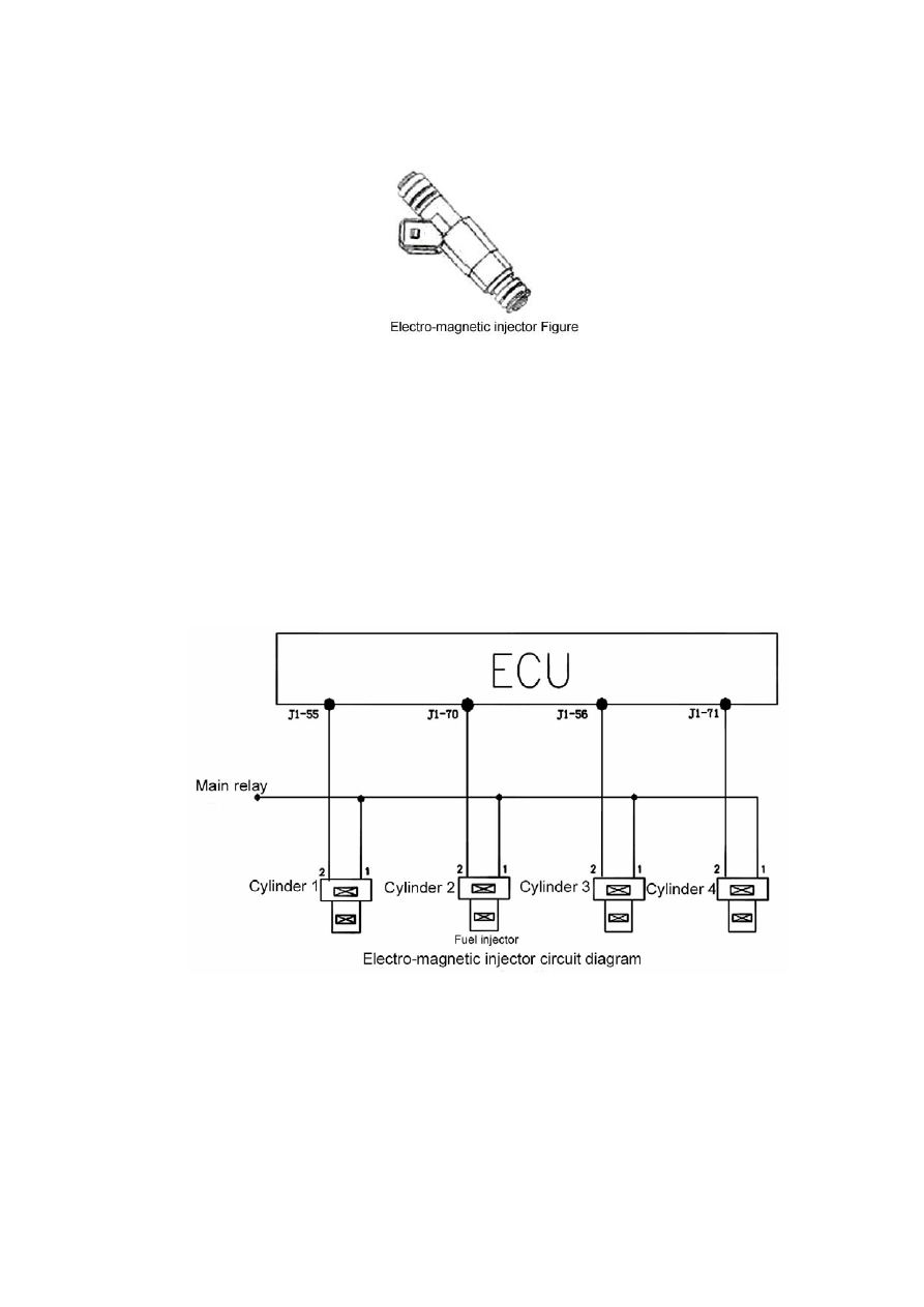
8. Electro-magnetic injecto

r  

(Fig. 1-13) 


Fig1-14 


Installation notes: 

The plugs for certain fuel injectors should be selected as per requirement. To 

facilitate installation, it is recommended to apply clean silicon-free oil on the surface of the upper 
O-ring connected to the fuel distribution pipe. Take care not to pollute the internal of the injector 
and the injection hole by the oil. Install the injector vertically into the injector seat and fix the 
injector on the seat with a clip.   

Note: 

For vehicles out of use for a long time, the adhesive gasoline within the injector can make 

33

the vehicle fail to start. 

(4) Trouble diagnosis:

 The electronic injection system will carry out trouble diagnosis for the 

driving stage of the fuel injector. When the driving stage of the injector is short or overloaded to the 
battery voltage, as well as short and open to the ground, the trouble mark level will be positioned. 
At this moment, the closed loop control and the self-learning pre-control of the oxygen sensor will 
be closed, while the self-learning data last time will be effective. The trouble mark level will be 
repositioned after the trouble being removed. 
 

9. Idle speed actuator stepper motor

 (Fig. 1-15) 


34

(3) Connection of wiring diagram 

(Fig. 1-16) 


voltage electricity, to produce spark to burn the mixture of fuel and air in the cylinder. 

(2) Separate ignition (grouped ignition): 

Based on the signal from the crankshaft/camshaft 

position sensor, the ECU controls the grounding of the three ignition coils respectively for the 
ignition of the engine. 

(3) Structure and principle:

 Consists of primary winding, secondary winding, iron core, housing, 

etc. When the battery is connected with the primary winding, the primary winding will be charged. 
When the circuit of the primary winding is cut down by the ECU, the charge will stop. Meanwhile, 
the high voltage electricity will be induced in the secondary winding.   


35

(4) Wiring diagram of the parts 

(Fig. 1-18) 


(1) Function: 

To control the air flow to clean the canister. The canister control valve is controlled by the 

ECU based on the engine load, electric pulse duration and frequency (duty cycle). The over-accumulated 
gasoline vapor in the activated canister will cause gasoline leakage and environmental pollution. Thus, 
the canister solenoid valve is designed to be opened properly to introduce the over-accumulated gasoline 
vapor into the intake pipe for combustion. 

(2) Structure and principle:

 Consists of solenoid coil, armature, valves, etc. A filter is considered 

for the inlet hole. The air volume flows through the canister control valve is affected by the duty 
cycle of the electric pulse output by the ECU, meanwhile, it is also affected by the pressure 

36


Content   ..  6  7  8  9   ..