Lexus LC500C (2024 year). Manual in english - page 8
 

  Index      Manuals     Lexus LC500C (2024 year). Manual in english


Search            copyright infringement  


Content      ..     6      7      8      9     ..


Lexus LC500C (2024 year). Manual in english - page 8


251

4-5. Using the driving support systems

4

Driving

2

Accelerate or decelerate, with 
accelerator pedal operation, to the 
desired vehicle speed (at or above 
approximately 20 mph [30 km/h]) 
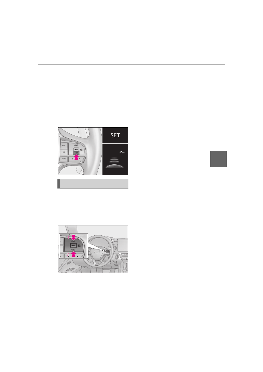
and press the “-SET” switch to set 
the speed.

Cruise control “SET” indicator will come 

on.
The vehicle speed at the moment the 

switch is released becomes the set speed.

Adjusting the set speed by the 
switch

To change the set speed, press the 
“+RES” or “-SET” switch until the 
desired set speed is displayed.

1

Increases the speed (Except when 
the vehicle has been stopped by 
system control in vehicle-to-vehicle 
distance control mode)

2

Decreases the speed

Fine adjustment: Press the switch.
Large adjustment: Press and hold the 
switch to change the speed, and 
release when the desired speed is 
reached.
In the vehicle-to-vehicle distance con-
trol mode, the set speed will be 
increased or decreased as follows:

For the U.S. mainland and Hawaii

Fine adjustment: By 1 mph (1.6 km/h)

*1

 or 1 

km/h (0.6mph)

*2

 each time the switch is 

pressed 
Large adjustment: Increases or decreases 
in 1mph (1.6 km/h)

*1

 or 1 km/h (0.6 mph)

*2


increments for as long as the switch is held

Except for the U.S. mainland and 
Hawaii

Fine adjustment: By 1 mph (1.6 km/h)

*1

 or 1 

km/h (0.6mph)

*2

 each time the switch is 

pressed 
Large adjustment: Increases or decreases 
in 5 mph (8 km/h)

*1

 or 5 km/h (3.1 mph)

*2


increments for as long as the switch is held

In the constant speed control mode 
(

P.254), the set speed will be 

increased or decreased as follows:

Fine adjustment: By 1 mph (1.6 km/h)

*1

 or 1 

km/h (0.6 mph)

*2

 each time the switch is 

pressed
Large adjustment: The speed will continue 
to change while the switch is held.

*1

: When the set speed is shown in “MPH”

*2

: When the set speed is shown in “km/h”

Increasing the set speed by the 
accelerator pedal

Adjusting the set speed

252

4-5. Using the driving support systems

1

Accelerate with accelerator pedal 
operation to the desired vehicle 
speed

2

Press the “-SET” switch

Pressing the switch changes the vehi-
cle-to-vehicle distance as follows:

1

Long

2

Medium

3

Short

If a vehicle is running ahead of you, the pre-
ceding vehicle mark 

 will also be dis-

played.

Select a distance from the table below. 
Note that the distances shown corre-
spond to a vehicle speed of 50 mph 
(80 km/h). Vehicle-to-vehicle dis-
tance increases/decreases in accor-
dance with vehicle speed. When the 
vehicle is stopped by system control, 
the vehicle stops at a certain vehicle-

to-vehicle distance depending on the 
situation.

After the vehicle ahead of you starts 
off, press the “+RES” switch.
Your vehicle will also resume follow-
up cruising if the accelerator pedal is 
depressed after the vehicle ahead of 
you starts off.

Changing the vehicle-to-vehicle 
distance (vehicle-to-vehicle dis-
tance control mode)

Vehicle-to-vehicle distance set-
tings (vehicle-to-vehicle dis-
tance control mode)

A

Distance options

Vehicle-to-vehicle 

distance

Long

Approximately 160 

ft. (50 m)

Medium

Approximately 130 

ft. (40 m)

Short

Approximately 100 

ft. (30 m)

Resuming follow-up cruising 
when the vehicle has been 
stopped by system control (vehi-
cle-to-vehicle distance control 
mode)

253

4-5. Using the driving support systems

4

Driving

1

Pressing the cancel switch cancels 
the speed control.

The speed control is also canceled when 
the brake pedal is depressed. (When the 
vehicle has been stopped by system con-
trol, depressing the brake pedal does not 
cancel the setting.)

2

Pressing the “+RES” switch 
resumes the cruise control and 
returns vehicle speed to the set 
speed.

When your vehicle is too close to a 
vehicle ahead, and sufficient automatic 
deceleration via the cruise control is 
not possible, the display will flash and 
the buzzer will sound to alert the 
driver. An example of this would be if 
another driver cuts in front of you while 
you are following a vehicle. Depress 
the brake pedal to ensure an appropri-
ate vehicle-to-vehicle distance.

Warnings may not occur when

In the following instances, warnings 
may not occur even when the vehicle-
to-vehicle distance is small.

When the speed of the preceding 
vehicle matches or exceeds your 
vehicle speed

When the preceding vehicle is trav-
eling at an extremely slow speed

Immediately after the cruise control 
speed was set

When depressing the accelerator 
pedal

While driving in vehicle-to-vehicle dis-
tance control mode, this function will 
reduce the vehicle speed, if it is deter-
mined to be necessary.

Function operation

When the steering wheel begins to be 
turned, the vehicle speed will begin 
being reduced. When the steering 
wheel is returned to the center posi-
tion, the vehicle speed reduction will 
end.
Depending on the situation, the vehicle 
speed will then return to the vehicle-to-

Canceling and resuming the 
speed control

Approach warning (vehicle-to-
vehicle distance control mode)

Curve speed reduction function

254

4-5. Using the driving support systems

vehicle distance control mode set 
speed.
In situations where vehicle-to-vehicle 
distance control needs to operate, 
such as when a preceding vehicle cuts 
in front of your vehicle, the curve 
speed reduction function will be can-
celed.

Operation display

Displayed when the vehicle speed is 
being reduced.

When the vehicle speed reduction ends, 
the display will disappear.

Changing the settings of the curve 
speed reduction function

The curve speed reduction function 
can be enabled/disabled and the vehi-
cle speed reduction strength can be 
adjusted on 

 (

P.110) of the multi-

information display.

The setting will change each time the “OK” 
meter control switch is pressed.

When constant speed control mode is 
selected, your vehicle will maintain a 
set speed without controlling the vehi-
cle-to-vehicle distance. Select this 

mode only when vehicle-to-vehicle 
distance control mode does not func-
tion correctly due to a dirty radar, etc.

1

With the cruise control off, press 
and hold the cruise control main 
switch for 1.5 seconds or more.

Immediately after the switch is pressed, the 

dynamic radar cruise control indicator will 

come on. Afterwards, it switches to the 

cruise control indicator.
Switching to constant speed control mode 

is only possible when operating the switch 

with the cruise control off.

2

Accelerate or decelerate, with 
accelerator pedal operation, to the 
desired vehicle speed (at or above 
approximately 20 mph [30 km/h]) 
and press the “-SET” switch to set 
the speed.

Cruise control “SET” indicator will come 

on.
The vehicle speed at the moment the 

switch is released becomes the set speed.
Adjusting the speed setting: 

P.251

Canceling and resuming the speed setting: 

Selecting constant speed con-
trol mode

255

4-5. Using the driving support systems

4

Driving

P.253

Dynamic radar cruise control with full-

speed range can be set when

The shift position is in D.

The desired set speed can be set when 

the vehicle speed is approximately 20 

mph (30 km/h) or more.

(However, when the vehicle speed is set 

while driving at below approximately 20 

mph [30 km/h], the set speed will be set 

to approximately 20 mph [30 km/h].)

Accelerating after setting the vehicle 

speed

The vehicle can accelerate by operating the 

accelerator pedal. After accelerating, the 

set speed resumes. However, during vehi-

cle-to-vehicle distance control mode, the 

vehicle speed may decrease below the set 

speed in order to maintain the distance to 

the preceding vehicle.

When the vehicle stops while follow-up 

cruising

Pressing the “+RES” switch while the 

vehicle ahead stops will resume follow-

up cruising if the vehicle ahead starts off 

within approximately 3 seconds after the 

switch is pressed.

If the vehicle ahead starts off within 3 sec-

onds after your vehicle stops, follow-up 

cruising will be resumed.

Automatic cancelation of vehicle-to-

vehicle distance control mode

Vehicle-to-vehicle distance control mode is 

automatically canceled in the following situ-

ations:

VSC is activated.

TRAC is activated for a period of time.

When the VSC or TRAC system is 

turned off.

The sensor cannot detect correctly 

because it is covered in some way.

When the brake control or output 

restriction control of a driving support 

system operates.

(For example: Pre-Collision System, 

Drive-Start Control)

The parking brake is operated.

The vehicle is stopped by system control 

on a steep incline.

The following are detected when the 

vehicle has been stopped by system con-

trol:

• The driver is not wearing a seat belt.

• The driver’s door is opened.

• The vehicle has been stopped for about 3 

minutes

If vehicle-to-vehicle distance control mode 

is automatically canceled for any reasons 

other than the above, there may be a mal-

function in the system. Contact your Lexus 

dealer.

Automatic cancelation of constant 

speed control mode

Constant speed control mode is automati-

cally canceled in the following situations:

Actual vehicle speed is more than 

approximately 10 mph (16 km/h) below 

the set vehicle speed.

Actual vehicle speed falls below approxi-

mately 20 mph (30 km/h).

VSC is activated.

TRAC is activated for a period of time.

When the VSC or TRAC system is 

turned off.

When the brake control or output 

restriction control of a driving support 

system operates.

(For example: Pre-Collision System, 

Drive-Start Control)

The parking brake is operated.

If constant speed control mode is automati-

cally canceled for any reasons other than 

the above, there may be a malfunction in 

the system. Contact your Lexus dealer.

256

4-5. Using the driving support systems

Situations in which the curve speed 

reduction function may not operate

In situations such as the following, the curve 

speed reduction function may not operate:

When the vehicle is being driven around 

a gentle curve

When the accelerator pedal is being 

depressed

When the vehicle is being driven around 

an extremely short curve

Brake operation

A brake operation sound may be heard and 

the brake pedal response may change, but 

these are not malfunctions.

Warning messages and buzzers for 

dynamic radar cruise control with full-

speed range

Warning messages and buzzers are used to 

indicate a system malfunction or to inform 

the driver of the need for caution while driv-

ing. If a warning message is shown on the 

multi-information display, read the message 

and follow the instructions. (

P.224, 394)

When the sensor may not be correctly 

detecting the vehicle ahead

In the case of the following and depending 

on the conditions, operate the brake pedal 

when deceleration of the system is insuffi-

cient or operate the accelerator pedal 

when acceleration is required. 

As the sensor may not be able to correctly 

detect these types of vehicles, the approach 

warning (

P.253) may not be activated.

Vehicles that cut in suddenly

Vehicles traveling at low speeds

Vehicles that are not moving in the same 

lane

Vehicles with small rear ends (trailers 

with no load on board, etc.)

Motorcycles traveling in the same lane

When water or snow thrown up by the 

surrounding vehicles hinders the detect-

ing of the sensor

When your vehicle is pointing upwards 

(caused by a heavy load in the luggage 

compartment, etc.)

Preceding vehicle has an extremely high 

ground clearance

Conditions under which the vehicle-to-

vehicle distance control mode may not 

function correctly

In the case of the following conditions, 

operate the brake pedal (or accelerator 

pedal, depending on the situation) as nec-

essary. 

As the sensor may not be able to correctly 

detect vehicles ahead, the system may not 

operate properly.

When the road curves or when the lanes 

are narrow

When steering wheel operation or your 

position in the lane is unstable

257

4-5. Using the driving support systems

4

Driving

When the vehicle ahead of you deceler-

ates suddenly

When driving on a road surrounded by a 

structure, such as in a tunnel or on a 

bridge

While the vehicle speed is decreasing to 

the set speed after the vehicle acceler-

ates by depressing the accelerator pedal

Situations in which the curve speed 

reduction function may not operate 

properly

In situations such as the following, the curve 

speed reduction function may not operate 

properly:

When the vehicle is being driven around 

a curve on an incline/decline

When the course of the vehicle differs 

from the shape of the curve

When the vehicle speed is excessively 

high when entering a curve

When the steering wheel is suddenly 

operated

1

Normal mode/Custom mode

Normal mode and custom mode are 
selected by pressing the driving mode 
select switch. Each time the switch is 
pressed, the driving mode changes 
between normal mode and custom mode. 
When custom mode is selected, the “Cus-
tom” indicator comes on.
Press the switch to change the driving 
mode to normal mode when not in normal 
mode.
• Normal mode
Provides an optimal balance of fuel econ-
omy, quietness, and dynamic performance. 
Suitable for city driving.
When the shift position is in D, an appropri-
ate gear for sporty driving may automati-

Driving mode select switch

The driving modes can be selected 
to suit driving condition.

Selecting the driving mode

258

4-5. Using the driving support systems

cally be selected according to driver 
performance and driving conditions.
• Custom  mode
Allows you to drive with the power train, 
chassis and air conditioning system func-
tions set to your preferred settings. 
Custom mode settings can only be 
changed on the drive mode customization 
display of the Center Display. (

P.459)

2

Comfort mode

By controlling the suspension, riding com-
fort is further enhanced. Suitable for city 
driving.
When not in comfort mode and the driving 
mode select switch is turned forward, the 
“Comfort” indicator comes on.

3

Eco drive mode

Helps the driver accelerate in an eco-
friendly manner and improve fuel economy 
through moderate throttle characteristics 
and by controlling the operation of the air 
conditioning system (heating/cooling).
When in comfort mode, if the driving mode 
select switch is turned forward, the “Eco” 
indicator comes on.

4

Sport mode

• SPORT  S  mode
Controls the transmission and engine to 
provide quick, powerful acceleration. This 
mode is suitable for when agile driving 
response is desired, such as when driving 
on roads with many curves.
When not in SPORT S mode, if the driving 
mode select switch is turned backward, the 
“Sport S” indicator comes on.
• SPORT  S+  mode
Provides earlier downshift timing than 
SPORT S mode in order to maintain a high 
engine speed and provides faster gear 
changes. This mode also changes the 
steering feel, suspension control and 
VDIM control, making it suitable for pow-

erful sporty driving.
When in SPORT S mode, if the driving 
mode select switch is turned backward, the 
“Sport S+” indicator comes on.

Operation of the air conditioning sys-

tem in Eco drive mode

Eco drive mode controls the heating/cool-

ing operations and fan speed of the air con-

ditioning system to enhance fuel efficiency. 

To improve air conditioning performance, 

perform the following operations:

Turn off eco air conditioning mode 

(

P.296)

Adjust the fan speed (

P.295)

Turn off Eco drive mode (

P.257)

Automatic deactivation of sport mode 

and custom mode

If the engine switch <power switch> is 

turned off after driving in sport mode or 

custom mode, the drive mode will be 

changed to normal mode.

Driving mode pop-up display

When the driving mode is changed, the 

selected driving mode will be temporarily 

displayed on the Center Display. (Except 

for Normal mode)
For Custom mode, select “Settings” on the 

display to customize the driving mode.

259

4-5. Using the driving support systems

4

Driving

Types of sensors

Except Convertible

Front corner sensors

Front center sensors

Rear corner sensors

Rear center sensors

Convertible

Front corner sensors

Front center sensors

Rear corner sensors

Rear center sensors

Display

When the sensors detect an obstacle, a 
graphic is shown on the Center Dis-
play depending on the position and dis-
tance to the obstacle.

Except Convertible

Display example:

Front corner sensor detection

Front center sensor detection

Rear corner sensor detection

Rear center sensor detection

Convertible

Display example:

Front corner sensor detection

Intuitive parking assist

The distance from your vehicle to 
nearby obstacles when parallel 
parking or maneuvering into a 
garage is measured by the sensors 
and communicated via the Center 
Display and a buzzer. Always check 
the surrounding area when using 
this system.

System components

A
B
C
D

A
B
C
D

A
B
C
D

A

260

4-5. Using the driving support systems

Front center sensor detection

Rear corner sensor detection

Rear center sensor detection

1

Press 

 or 

 of the meter con-

trol switches, and select 

.

2

Press 

 or 

 of the meter con-

trol switches, and select “Parking 
Assist”, and press “OK”.

When the intuitive parking assist turn 
on, the intuitive parking assist indicator 
comes on to inform the driver that the 
system is operational.

The intuitive parking assist can be oper-

ated when

Front center sensors:

• The engine switch <power switch> is in 

ON.

• The shift position is in a position other 

than P or R.

• The vehicle speed is less than about 6 

mph (10 km/h).

Front corner sensors:

• The engine switch <power switch> is in 

ON.

• The shift position is in a position other 

than P.

• The vehicle speed is less than about 6 

mph (10 km/h). 

(At any speed when the shift position is in 

R)

Rear corner and rear center sensors:

• The engine switch <power switch> is in 

ON.

• The shift position is in R.

Muting the buzzer sound

To mute the buzzer sound:

The buzzer can be temporarily muted by 

pressing “OK” of the meter control 
switches while an obstacle detection dis-
play is shown on the Center Display.

To cancel the mute:

Mute will be automatically canceled in the 
following situations.
• When the shift position is changed 

(except shifting from D to N, or N to D)

• When the vehicle speed has reached or 

exceeded 6 mph (10 km/h) with the shift 

position in D

• When the intuitive parking assist is turned 

off once and turned on again

• When the engine switch <power switch> 

is turned off once and turned to ON 

again

If “Clean Parking Assist Sensor” is dis-

played on the multi-information display

A sensor may be dirty or covered with snow 

or ice. In such cases, if it is removed from 

the sensor, the system should return to nor-

mal.
Also, due to the sensor being frozen at low 

temperatures, a malfunction display may 

appear or an obstacle may not be detected. 

If the sensor thaws out, the system should 

return to normal.

If “Parking Assist Malfunction” or 

“Parking Assist Malfunction Visit Your 

Dealer” is displayed on the multi-infor-

mation display

There is a malfunction and the device may 

not be working properly.
Have the vehicle inspected by your Lexus 

dealer.

Sensor detection information

The sensor’s detection areas are limited 

to the areas around the vehicle’s front 

and rear bumpers.

The following situations may occur 

during use.

• Depending on the shape of the object 

and other factors, the detection distance 

may shorten, or detection may be impos-

sible.

• Detection may be impossible if static 

objects draw too close to the sensor.

• There will be a short delay between static 

Turning intuitive parking assist 
on/off

B
C
D

261

4-5. Using the driving support systems

4

Driving

object detection and display (warning 

buzzer sounds). Even at low speeds, 

there is a possibility that the object will 

come within 1.0 ft. (30 cm) before the 

display is shown and the warning buzzer 

sounds.

• It might be difficult to hear the buzzer due 

to the volume of the audio system or air 

flow noise of the air conditioning system.

• It may be difficult to hear the sound of this 

system due to the buzzers of other sys-

tems.

Objects which the system may not prop-

erly detect

The shape of the object may prevent the 

sensor from detecting it. Pay particular 

attention to the following objects:

Wires, fences, ropes, etc.

Cotton, snow and other materials that 

absorb sound waves

Sharply-angled objects

Low objects

Tall objects with upper sections project-

ing outwards in the direction of your vehi-

cle

Situations in which the system may not 

operate properly

Certain vehicle conditions and the sur-

rounding environment may affect the ability 

of a sensor to correctly detect objects. Par-

ticular instances where this may occur are 

listed below.

There is dirt, snow, water drops or ice on 

a sensor. (Cleaning the sensors will 

resolve this problem.)

A sensor is frozen. (Thawing the area will 

resolve this problem.)

In especially cold weather, if a sensor is fro-
zen the sensor display may be displayed 
abnormally, or objects, such as a wall, may 
not be detected.

When a sensor or the area around a sen-

sor is extremely hot or cold.

On an extremely bumpy road, on an 

incline, on gravel, or on grass.

When vehicle horns, vehicle detectors, 

motorcycle engines, air brakes of large 

vehicles, the clearance sonar of other 

vehicles or other devices which produce 

ultrasonic waves are near the vehicle.

A sensor is coated with a sheet of spray 

or heavy rain.

If objects draw too close to the sensor.

When a pedestrian is wearing clothing 

that does not reflect ultrasonic waves (ex. 

skirts with gathers or frills).

When objects that are not perpendicular 

to the ground, not perpendicular to the 

vehicle traveling direction, uneven, or 

waving are in the detection range.

Strong wind is blowing.

When driving in inclement weather such 

as fog, snow or a sandstorm.

When an object that cannot be detected 

is between the vehicle and a detected 

object.

If an object such as a vehicle, motorcycle, 

bicycle or pedestrian cuts in front of the 

vehicle or runs out from the side of the 

vehicle.

If the orientation of a sensor has been 

changed due to a collision or other 

impact.

When equipment that may obstruct a 

sensor is installed, such as a towing eye-

let, bumper protector (an additional trim 

strip, etc.), bicycle carrier, or snow plow.

If the front of the vehicle is raised or low-

ered due to the carried load.

If the vehicle cannot be driven in a stable 

manner, such as when the vehicle has 

been in an accident or is malfunctioning.

262

4-5. Using the driving support systems

When tire chains, a compact spare tire or 

an emergency tire puncture repair kit are 

used.

Situations in which the system may 

operate even if there is no possibility of a 

collision

In some situations, such as the following, the 

system may operate even though there is 

no possibility of a collision.

When driving on a narrow road.

When driving toward a banner, flag, low-

hanging branch or boom barrier (such as 

those used at railroad crossings, toll 

gates and parking lots).

When there is a rut or hole in the surface 

of the road.

When driving on a metal cover (grating), 

such as those used for drainage ditches.

When driving up or down a steep slope.

If a sensor is hit by a large amount of 

water, such as when driving on a flooded 

road.

There is dirt, snow, water drops or ice on 

a sensor. (Cleaning the sensors will 

resolve this problem.)

A sensor is coated with a sheet of spray 

or heavy rain.

When driving in inclement weather such 

as fog, snow or a sandstorm.

When strong winds are blowing.

When vehicle horns, vehicle detectors, 

motorcycle engines, air brakes of large 

vehicles, the clearance sonar of other 

vehicles or other devices which produce 

ultrasonic waves are near the vehicle.

If the front of the vehicle is raised or low-

ered due to the carried load.

If the orientation of a sensor has been 

changed due to a collision or other 

impact.

The vehicle is approaching a tall or 

curved curb.

Driving close to columns (H-shaped steel 

beams, etc.) in multi-story parking 

garages, construction sites, etc.

If the vehicle cannot be driven in a stable 

manner, such as when the vehicle has 

been in an accident or is malfunctioning.

On an extremely bumpy road, on an 

incline, on gravel, or on grass.

When tire chains, a compact spare tire or 

an emergency tire puncture repair kit are 

used.

Customization

Some functions can be customized. 

(

P.459)

WARNING

Cautions regarding the use of the 

system

There is a limit to the degree of recogni-

tion accuracy and control performance 

that this system can provide, do not 

overly rely on this system. The driver is 

always responsible for paying attention 

to the vehicle’s surroundings and driving 

safely.

263

4-5. Using the driving support systems

4

Driving

WARNING

To ensure the system can operate 

properly

Observe the following precautions. 

Failing to do so may result in the vehicle 

being unable to be driven safely and pos-

sibly cause an accident.

Do not damage the sensors, and 

always keep them clean.

Do not attach a sticker or install an 

electronic component, such as a back-

lit license plate (especially fluorescent 

type), fog lights, fender pole or wire-

less antenna near a radar sensor.

Do not subject the surrounding area of 

the sensor to a strong impact. If sub-

jected to an impact, have the vehicle 

inspected by your Lexus dealer. If the 

front or rear bumper needs to be 

removed/installed or replaced, con-

tact your Lexus dealer.

Do not modify, disassemble or paint 

the sensors.

Do not attach a license plate cover.

Keep your tires properly inflated.

When to disable the function

In the following situations, disable the 

function as it may operate even though 

there is no possibility of a collision.

Failing to observe the warnings above.

A non-genuine Lexus suspension 

(lowered suspension, etc.) is installed.

Notes when washing the vehicle

Do not apply intensive bursts of water or 

steam to the sensor area.
Doing so may result in the sensor mal-

functioning.

When using a high pressure washer to 

wash the vehicle, do not spray the sen-

sors directly, as doing so may cause a 

sensor to malfunction.

When using steam to clean the vehi-

cle, do not direct steam too close to 

the sensors as doing so may cause a 

sensor to malfunction.

NOTICE

When using intuitive parking assist

In the following situations, the system 

may not function correctly due to a sen-

sor malfunction etc. Have the vehicle 

checked by your Lexus dealer.

The intuitive parking assist operation 

display flashes or shows continuously, 

and a beep sounds when no obstacles 

are detected.

If the bumper or grille collides with 

something.

If the display flashes or shows continu-

ously without beeping, except when 

the mute function has been turned on.

If a display error occurs, first check the 

sensor. 

If the error occurs even when there is 

no ice, snow or mud on the sensor, it is 

likely that the sensor is malfunctioning.

264

4-5. Using the driving support systems

Detection range of the sensors

Approximately 3.3 ft. (100 cm)

Approximately 4.9 ft. (150 cm)

Approximately 2.0 ft. (60 cm)

The diagram shows the detection range of 
the sensors. Note that the sensors cannot 
detect obstacles that are extremely close 
to the vehicle.
The range of the sensors may change 
depending on the shape of the object etc.

The distance and buzzer

Sensor detection display, obsta-
cle distance

A
B
C

Approximate distance to obstacle

Buzzer

Front center sensor:
Approximately 3.3 ft. (100 cm) to 2.0 ft. (60 cm)
Rear center sensor
Approximately 4.9 ft. (150cm) to 2.0 ft. (60 cm)

Slow

Front center sensor:
Approximately 2.0 ft. (60 cm) to 1.6 ft. (50 cm)
Except front center sensor:
Approximately 2.0 ft. (60 cm) to 1.5 ft. (45 cm)

Medium

Front center sensor:
Approximately 1.6 ft. (50 cm) to 1.3 ft. (40 cm)
Except front center sensor:
Approximately 1.5 ft. (45 cm) to 1.1 ft. (35 cm)

Fast

265

4-5. Using the driving support systems

4

Driving

Buzzer operation and distance to 
an obstacle

A buzzer sounds when the sensors are 
operating.

The buzzer beeps faster as the vehi-
cle approaches an obstacle. When 
the vehicle comes within the follow-
ing distance of the obstacle, the 
buzzer sounds continuously:

• Front center sensors: Approximately 1.3 

ft. (40 cm)

• Except front center sensor: Approxi-

mately 1.1 ft. (35 cm)

When 2 or more obstacles are 
detected simultaneously, the buzzer 
system responds to the nearest 
obstacle. If one or both come within 
the above distances, the beep will 
repeat a long tone, followed by fast 
beeps.

Front center sensor:
Approximately 1.3 ft. (40 cm) to 1.0 ft. (30 cm)
Except front center sensor:
Approximately 1.1 ft. (35 cm) to 1.0 ft. (30 cm)

Continuous

Less than approximately 1.0 ft. (30 cm)

Approximate distance to obstacle

Buzzer

266

4-5. Using the driving support systems

Except Convertible

Multi-information display

Turning the BSM function/RCTA function 
on/off.
The RCTA function is available when the 
BSM function is on.

Outside rear view mirror indicators

BSM function: 
When a vehicle is detected in a blind spot 
of the outside rear view mirrors or 
approaching rapidly from behind into a 
blind spot, the outside rear view mirror 
indicator on the detected side will illumi-
nate. If the turn signal lever is operated 
toward the detected side, the outside rear 
view mirror indicator will flash.
RCTA function: 
When a vehicle approaching from the right 
or left at the rear of the vehicle is detected, 
both outside rear view mirror indicators 
will flash.

BSM indicator/RCTA indicator

When the BSM function/RCTA function is 
turned on, the indicator comes on.

Monitor screen display (RCTA 
function only)

If a vehicle approaching from the right or 
left at the rear of the vehicle is detected, 
the RCTA icon (

P.271) for the detected 

side will be displayed on the monitor 
screen. This illustration shows an example 
of a vehicle approaching from both sides of 
the vehicle.

RCTA buzzer (RCTA function 
only)

If a vehicle approaching from the right or 
left at the rear of the vehicle is detected, a 
buzzer will sound. The buzzer also sounds 
for approximately 1 second immediately 
after the BSM function is operated to turn 
the system on.

BSM (Blind Spot Monitor)

The Blind Spot Monitor uses the 
sensors installed behind the rear 
bumper. The system is intended to 
assist the driver check areas that 
are not easily visible. The system 
has the following 2 functions:

The BSM (Blind Spot Monitor) 
function

Assists the driver in making a deci-
sion when changing lanes

The RCTA (Rear Cross Traffic 
Alert) function

Assists the driver when backing up

These functions use same sensors.

System components

A

B

C

D

E

267

4-5. Using the driving support systems

4

Driving

Convertible

Multi-information display

Turning the BSM function/RCTA function 
on/off.
The RCTA function is available when the 
BSM function is on.

Outside rear view mirror indicators

BSM function: 
When a vehicle is detected in a blind spot 
of the outside rear view mirrors or 
approaching rapidly from behind into a 
blind spot, the outside rear view mirror 
indicator on the detected side will illumi-
nate. If the turn signal lever is operated 
toward the detected side, the outside rear 
view mirror indicator will flash.
RCTA function: 
When a vehicle approaching from the right 
or left at the rear of the vehicle is detected, 
both outside rear view mirror indicators 
will flash.

BSM indicator/RCTA indicator

When the BSM function/RCTA function is 
turned on, the indicator comes on.

Monitor screen display (RCTA 
function only)

If a vehicle approaching from the right or 
left at the rear of the vehicle is detected, 
the RCTA icon (

P.271) for the detected 

side will be displayed on the monitor 
screen. This illustration shows an example 
of a vehicle approaching from both sides of 
the vehicle.

RCTA buzzer (RCTA function 
only)

If a vehicle approaching from the right or 
left at the rear of the vehicle is detected, a 
buzzer will sound. The buzzer also sounds 
for approximately 1 second immediately 
after the BSM function is operated to turn 
the system on.

1

Press 

 or 

 of the meter con-

trol switches, select 

.

2

Press 

 or 

 of the meter con-

trol switches, select “BSM”, and 
then press “OK”.

3

Press 

 or 

 of the meter con-

trol switches, select “BSM” or 
“RCTA”, and press “OK”.

Outside rear view mirror indicator visi-

bility

In strong sunlight, the outside rear view mir-

ror indicator may be difficult to see.

Hearing the RCTA buzzer

The RCTA buzzer may be difficult to hear 

over loud noises, such as if the audio system 

volume is high.

A

B

C

Turning the BSM func-
tion/RCTA function on/off

D

E

268

4-5. Using the driving support systems

When “Blind Spot Monitor Unavailable” 

is shown on the multi-information dis-

play

Water, snow, mud, etc., may be built up in 

the vicinity of the sensor area of bumper. 

(

P.268) Removing the water, snow, 

mud, etc., from the vicinity of the sensor 

area bumper should return it to normal.
Also, the sensor may not function normally 

when used in extremely hot or cold 

weather.

When “Blind Spot Monitor System Mal-

function” is shown on the multi-informa-

tion display

There may be a sensor malfunction or volt-

age abnormality. Have the vehicle 

inspected at your Lexus dealer.

Customization

Some functions can be customized. (Cus-

tomizable features: 

P.459)

WARNING

To ensure the system can operate 

properly

Blind Spot Monitor sensors are installed 

behind the left and right sides of the rear 

bumper respectively. Observe the fol-

lowing to ensure the Blind Spot Monitor 

can function correctly.

Keep the sensors and the surrounding 

areas on the rear bumper clean at all 

times. 

If a sensor or its surrounding area on 

the rear bumper is dirty or covered 

with snow, the Blind Spot Monitor may 

not operate and a warning message 

(

P.268) will be displayed. In this sit-

uation, clear off the dirt or snow and 

drive the vehicle with the operation 

conditions of the BSM function 

(

P.270) satisfied for approximately 

10 minutes. If the warning message 

does not disappear, have the vehicle 

inspected by your Lexus dealer.

Do not subject a sensor or its sur-

rounding area on the rear bumper to a 

strong impact. 

If a sensor is moved even slightly off 

position, the system may malfunction 

and vehicles may not be detected cor-

rectly. 

In the following situations, have your 

vehicle inspected by your Lexus 

dealer.

• A sensor or its surrounding area is 

subject to a strong impact.

• If the surrounding area of a sensor is 

scratched or dented, or part of them 

has become disconnected.

Do not disassemble the sensor.

Do not attach stickers to the sensor or 

surrounding area on the rear bumper.

Do not modify the sensor or surround-

ing area on the rear bumper.

Do not paint the rear bumper any 

color other than an official Lexus color.

269

4-5. Using the driving support systems

4

Driving

Operation of the BSM function

The BSM function uses radar sensors to detect the following vehicles traveling in 
adjacent lanes and advises the driver of the presence of such vehicles via the indi-
cators on the outside rear view mirrors.

Vehicles that are traveling in areas that are not visible using the outside rear 
view mirrors (the blind spots)

Vehicles that are approaching rapidly from behind in areas that are not visible 
using the outside rear view mirrors (the blind spots)

BSM function detection areas

The areas that vehicles can be detected in are outlined below.

The range of each detection area is:

Approximately 1.6 ft. (0.5 m) to 11.5 ft. (3.5 m) from either side of the vehicle

*1

Approximately 3.3 ft. (1 m) forward of the rear bumper

Approximately 9.8 ft. (3 m) from the rear bumper

Approximately 9.8 ft. (3 m) to 197 ft. (60 m) from the rear bumper

*2

*1

: The area between the side of the vehicle and 1.6 ft. (0.5 m) from the side of the vehicle 

cannot be detected.

BSM function

A

B

A
B
C
D

270

4-5. Using the driving support systems

*2

: The greater the difference in speed between your vehicle and the detected vehicle is, 

the farther away the vehicle will be detected, causing the outside rear view mirror indi-
cator to illuminate or flash.

The BSM function is operational when

The BSM function is operational when all of 

the following conditions are met:

The BSM function is on.

The shift position is in a position other 

than R.

The vehicle speed is greater than 

approximately 7 mph (10 km/h).

The BSM function will detect a vehicle 

when

The BSM function will detect a vehicle pres-

ent in the detection area in the following sit-

uations:

A vehicle in an adjacent lane overtakes 

your vehicle.

You overtake a vehicle in adjacent lane 

slowly.

Another vehicle enters the detection 

area when it changes lanes.

Conditions under which the system will 

not detect a vehicle

The BSM function is not designed to detect 

the following types of vehicles and/or 

objects:

Small motorcycles, bicycles, pedestrians, 
etc.

*

Vehicles traveling in the opposite direc-

tion

Guardrails, walls, signs, parked vehicles 
and similar stationary objects

*

Following vehicles that are in the same 
lane

*

Vehicles traveling 2 lanes away from 
your vehicle

*

Vehicles which are being overtaken rap-
idly by your vehicle.

*

*

: Depending on the conditions, detection 

of a vehicle and/or object may occur.

Conditions under which the system may 

not function correctly

The BSM function may not detect vehi-

cles correctly in the following situations:

• When the sensor is misaligned due to a 

strong impact to the sensor or its sur-

rounding area

• When mud, snow, ice, a sticker, etc. is 

covering the sensor or surrounding area 

on the rear bumper

• When driving on a road surface that is 

wet with standing water during bad 

weather, such as heavy rain, snow, or fog

• When multiple vehicles are approaching 

with only a small gap between each vehi-

cle

• When the distance between your vehicle 

and a following vehicle is short

• When there is a significant difference in 

speed between your vehicle and the 

vehicle that enters the detection area

• When the difference in speed between 

your vehicle and another vehicle is 

changing

• When a vehicle enters a detection area 

traveling at about the same speed as your 

vehicle

• As your vehicle starts from a stop, a vehi-

cle remains in the detection area

• When driving up and down consecutive 

steep inclines, such as hills, dips in the 

road, etc.

• When driving on roads with sharp bends, 

consecutive curves, or uneven surfaces

• When vehicle lanes are wide, or when 

driving on the edge of a lane, and the 

vehicle in an adjacent lane is far away 

from your vehicle

• When an accessory (such as a bicycle 

carrier) or towing eyelet is installed to the 

rear of the vehicle

• When there is a significant difference in 

height between your vehicle and the 

vehicle that enters the detection area

• Immediately after the BSM function is 

turned on

Instances of the BSM function unneces-

sarily detecting a vehicle and/or object 

may increase in the following situations:

271

4-5. Using the driving support systems

4

Driving

• When the sensor is misaligned due to a 

strong impact to the sensor or its sur-

rounding area

• When the distance between your vehicle 

and a guardrail, wall, etc. that enters the 

detection area is short

• When driving up and down consecutive 

steep inclines, such as hills, dips in the 

road, etc.

• When vehicle lanes are narrow, or when 

driving on the edge of a lane, and a vehi-

cle traveling in a lane other than the adja-

cent lanes enters the detection area

• When driving on roads with sharp bends, 

consecutive curves, or uneven surfaces

• When the tires are slipping or spinning

• When the distance between your vehicle 

and a following vehicle is short

• When an accessory (such as a bicycle 

carrier) or towing eyelet is installed to the 

rear of the vehicle

Operation of the RCTA function

The RCTA function uses radar sensors to detect vehicles approaching from the 
right or left at the rear of the vehicle and alerts the driver of the presence of such 
vehicles by flashing the outside rear view mirror indicators and sounding a buzzer.

Approaching vehicles

Detection areas of approaching vehicles

RCTA icon display

When a vehicle approaching from the 
right or left at the rear of the vehicle is 
detected, the following will be dis-

played on the monitor screen.
Example: Vehicles are approaching 
from both sides of the vehicle

WARNING

Cautions regarding the use of the 

function

The driver is solely responsible for safe 

driving. Always drive safely, taking care 

to observe your surroundings.
The BSM function is a supplementary 

function which alerts the driver that a 

vehicle is in a blind spot of the outside 

rear view mirrors or is approaching rap-

idly from behind into a blind spot. Do not 

overly rely on the BSM function. As the 

function cannot judge if it is safe to 

change lanes, over reliance could lead to 

an accident resulting in death or serious 

injury.
As the system may not function correctly 

under certain conditions, the driver’s 

own visual confirmation of safety is nec-

essary.

RCTA function

A
B

272

4-5. Using the driving support systems

RCTA function detection areas

The areas that vehicles can be detected in are outlined below.

The buzzer can alert the driver of 
faster vehicles approaching from far-
ther away.
Example:

The RCTA function is operational when

The RCTA function operates when all of the 

following conditions are met:

The RCTA function is on.

The shift position is in R.

The vehicle speed is less than approxi-

mately 9 mph (15 km/h).

The approaching vehicle speed is 

between approximately 5 mph (8 km/h) 

and 34 mph (56 km/h).

Conditions under which the system will 

not detect a vehicle

The RCTA function is not designed to 

detect the following types of vehicles 

and/or objects:

Vehicles approaching from directly 

behind

Vehicles backing up in a parking space 

next to your vehicle

Vehicles that the sensors cannot detect 

due to obstructions

Guardrails, walls, signs, parked vehicles 
and similar stationary objects

*

Approaching vehi-

cle speed

 Approximate 

alert distance

34 mph (56 km/h) 

(fast)

98 ft. (30 m)

5 mph (8 km/h) 

(slow)

13 ft. (4 m)

A

273

4-5. Using the driving support systems

4

Driving

Small motorcycles, bicycles, pedestrians, 
etc.

*

Vehicles moving away from your vehicle

Vehicles approaching from the parking 
spaces next to your vehicle

*

The distance between the sensor and 

approaching vehicle gets too close

*

: Depending on the conditions, detection 

of a vehicle and/or object may occur.

Situations in which the system may not 

operate properly

The RCTA function may not detect vehicles 

correctly in the following situations:

When the sensor is misaligned due to a 

strong impact to the sensor or its sur-

rounding area.

When mud, snow, ice, a sticker, etc., is 

covering the sensor or surrounding area 

on the rear bumper.

When driving on a road surface that is 

wet with standing water during bad 

weather, such as heavy rain, snow, or fog.

When multiple vehicles are approaching 

with only a small gap between each vehi-

cle.

When a vehicle is approaching at high 

speed.

When equipment that may obstruct a 

sensor is installed, such as a towing eye-

let, bumper protector (an additional trim 

strip, etc.), bicycle carrier, or snow plow.

When backing up on a slope with a sharp 

change in grade.

When backing out of a sharp angle park-

ing spot.

When towing a trailer.

When there is a significant difference in 

height between your vehicle and the 

vehicle that enters the detection area.

When a sensor or the area around a sen-

sor is extremely hot or cold.

If the suspension has been modified or 

tires of a size other than specified are 

installed.

If the front of the vehicle is raised or low-

ered due to the carried load.

When turning while backing up.

When a vehicle turns into the detection 

area.

274

4-5. Using the driving support systems

Situations in which the system may 

operate even if there is no possibility of a 

collision

Instances of the RCTA function unneces-

sarily detecting a vehicle and/or object may 

increase in the following situations:

When the parking space faces a street 

and vehicles are being driven on the 

street.

When the distance between your vehicle 

and metal objects, such as a guardrail, 

wall, sign, or parked vehicle, which may 

reflect electrical waves toward the rear of 

the vehicle, is short.

When equipment that may obstruct a 

sensor is installed, such as a towing eye-

let, bumper protector (an additional trim 

strip, etc.), bicycle carrier, or snow plow.

When a vehicle passes by the side of your 

vehicle.

When a detected vehicle turns while 

approaching the vehicle.

When there are spinning objects near 

your vehicle such as the fan of an air con-

ditioning unit.

When water is splashed or sprayed 

toward the rear bumper, such as from a 

sprinkler.

Moving objects (flags, exhaust fumes, 

large rain droplets or snowflakes, rain 

water on the road surface, etc.).

When the distance between your vehicle 

and a guardrail, wall, etc., that enters the 

detection area is short.

Gratings and gutters.

When a sensor or the area around a sen-

sor is extremely hot or cold.

If the suspension has been modified or 

tires of a size other than specified are 

installed.

If the front of the vehicle is raised or low-

ered due to the carried load.

275

4-5. Using the driving support systems

4

Driving

*

: If equipped

Multi-information display (

P.110)

Displays the status of the active rear wing.

Active rear wing switch

Operates the active rear wing manually.

Indicator

Illuminates when the active rear wing is 
raised and turns off when it is retracted.

The active rear wing can be operated 

when

The engine switch <power switch> is in 

WARNING

Cautions regarding the use of the 

function

There is a limit to the degree of recogni-

tion accuracy and control performance 

that this system can provide, do not 

overly rely on this system. The driver is 

always responsible for paying attention 

to the vehicle’s surroundings and driving 

safely. (

P.271)

To ensure the system can operate 

properly

P.268

Active rear wing

*

The vehicle is equipped with an 
active rear wing that operates 
automatically while the vehicle is 
being driven. This active rear wing 
enhances aerodynamic perfor-
mance, especially at high speeds, 
contributing to a more stable ride.
The active rear wing can be con-
trolled manually using a switch.

System components

A

B

C

276

4-5. Using the driving support systems

ON.

The trunk is closed.

The active rear wing has been activated 

in a customized setting.

Conditions which stop the operation

In the following situations operation of the 

active rear wing will stop:

The engine switch <power switch> is 

turned to ACC or off while the active 

rear wing is operating.

The trunk is opened while the active rear 

wing is operating.

The raising operation of the active rear 

wing is interrupted by an object, etc.

The active rear wing is operated in an 

unusual manner causing it to stop at an 

irregular position.

In such cases, pressing the active rear wing 

switch will fully raise the active rear wing. 

Or, begin driving the vehicle and the active 

rear wing will raise automatically when the 

vehicle speed reaches 16 mph (25 km/h).

When there is a malfunction in the sys-

tem

A warning message will be displayed on the 

multi-information display. (

P.394)

Customization

The active rear wing can be turned on/off. 

(Customizable features: 

P.459)

The active rear wing will operate auto-
matically at the following speeds 
according to the selected driving 
mode (

P.257).

(Always observe the legal speed limit 
when driving on public roads.)

When other than Eco drive mode is 
selected
Up: Approximately 50 mph (80 
km/h)
Down: Approximately 25 mph (40 
km/h)

When Eco drive mode is selected
Up: Approximately 80 mph (130 
km/h)
Down: Approximately 25 mph (40 
km/h)

Operate the active rear wing switch to 
raise/retract the active rear wing man-
ually.
The active rear wing retracts when it is 
raised and raises when retracted.
However, the active rear wing does 
not respond to switch operations while 
the active rear wing is operating.

NOTICE

To prevent system damage

Do not apply pressure to the active 

rear wing when pushing or pulling the 

vehicle.

Do not lean on the active rear wing.

Do not attach any accessories or other 

objects to the active rear wing.

Do not modify or disassemble the 

active rear wing.

Do not subject the active rear wing to 

severe impact.

To prevent 12-volt battery discharge

Do not operate the active rear wing 

repeatedly while the engine <hybrid sys-

tem> is turned off.

Automatic operation

Changing to manual operation

277

4-5. Using the driving support systems

4

Driving

*

: Press and hold the switch until the indi-

cator turns off. If the switch is released 
while the active rear wing is moving, it 
will return to the raised position auto-
matically.

Restoring automatic operation after the 

active rear wing is operated manually

If the active rear wing is operated manually, 

automatic operation will resume according 

to the vehicle speed.

Vehicle speed

Up/Down

0 mph (0 km/h) 

(vehicle stopped)

Press/Press and 

hold

*

Approximately 0 – 

12 mph (0 – 20 

km/h)

Operation not pos-

sible

Approximately 12 – 

75 mph (20 – 120 

km/h)

Press/Press

Approximately 75 

mph (120 km/h) or 

more

Operation not pos-

sible

WARNING

When manually operating the active 

rear wing

Observe the following precautions 

before operating the active rear wing. 

Failure to do so may result in death or 

serious injury.

Ensure that the surrounding area is 

free of any objects that may come into 

contact with or get caught on the 

active rear wing.

If there are people near the active rear 

wing, make sure that there is no possi-

bility of their clothing, personal 

belongings or body parts getting 

caught. Children especially should be 

warned not to touch the active rear 

wing while it is being operated.

If there is a risk that an object may 

become caught on the active rear 

wing during operation, stop operation 

immediately.

278

4-5. Using the driving support systems

*

: If equipped

Fixed rear wing

The rear wing uses CFRP (Carbon Fiber 

Reinforced Plastic) parts, therefore pay 

attention to the following:

As the CFRP parts may change color if 

they are exposed to ultraviolet rays for 

extended periods of time, Lexus recom-

mends that your vehicle be stored in a 

place where it will not be exposed to 

direct sunlight.

Do not use wax that contains abrasives.

Do not use automatic car washes as they 

may scratch the CFRP parts and damage 

the paint, or may damage the rear wing.

To close the trunk, press the portions 

 of the rear wing.

Fixed rear wing

*

Installing a fixed rear wing will 
increase aerodynamic perfor-
mance when driving and will help to 
improve driving stability.

WARNING

When opening and closing the trunk

Observe the following precautions. Fail-

ure to do so may cause injury or serious 

damage.

Be careful that you do not bump the 

edge of the rear wing with your hands, 

arms, face or other parts of your body.

Do not leave your hand between the 

rear wing and trunk lid while opening 

the trunk. Your hand, arm or other part 

of your body may get caught when 

opening the trunk.

Do not sit on or lean against the rear 

wing, or place an excessive load on it. 

Failure to do so may damage the rear 

wing.

Do not attach any accessories other 

than genuine Lexus parts to the trunk 

lid. Such additional weight on the trunk 

lid may cause the lid to suddenly shut 

again after it is opened, dropping 

down on your head or body.

Disassembly and modification

Do not disassemble or modify the rear 

wing as doing so may reduce driving sta-

bility.

NOTICE

To prevent damage to the rear wing

Observe the following precautions. Fail-

ure to do so may damage the rear wing.

Do not place heavy objects on the rear 

wing, sit on or lean against it, or place 

an excessive load on it.

Do not strike the edge of the rear wing 

with solid objects or subject it to strong 

impact.

Do not hold the edge of the rear wing 

while opening or closing the trunk.

Disassembly and modification

Do not disassemble or modify the rear 

wing as doing so may cause water to 

enter the trunk.

When closing the trunk

A

279

4-5. Using the driving support systems

4

Driving

ECB (Electronically Controlled 
Brake System)

The electronically controlled system 
generates braking force correspond-
ing to the brake operation

ABS (Anti-lock Brake System)

Helps to prevent wheel lock when the 
brakes are applied suddenly, or if the 
brakes are applied while driving on a 
slippery road surface

Brake assist

Generates an increased level of brak-
ing force after the brake pedal is 
depressed when the system detects a 
panic stop situation

VSC (Vehicle Stability Control)

Helps the driver to control skidding 
when swerving suddenly or turning on 
slippery road surfaces

TRAC (Traction Control)

Helps to maintain drive power and 
prevent the drive wheels from spinning 
when starting the vehicle or accelerat-

Driving assist systems

To keep driving safety and perfor-
mance, the following systems oper-
ate automatically in response to 
various driving situations. Be 
aware, however, that these systems 
are supplementary and should not 
be relied upon too heavily when 
operating the vehicle.

Summary of the driving assist 
systems

280

4-5. Using the driving support systems

ing on slippery roads

Active Cornering Assist (ACA) (if 
equipped)

Helps to prevent the vehicle from drift-
ing to the outer side by performing 
inner wheel brake control when 
attempting to accelerate while turning

Hill-start assist control

Helps to reduce the backward move-
ment of the vehicle when starting on an 
uphill

VGRS (Variable Gear Ratio Steer-
ing) (if equipped)

Adjusts the front wheel turning angle in 
accordance with the vehicle speed and 
steering wheel movement

DRS (Dynamic Rear Steering) (if 
equipped)

Contributes to the turning characteris-
tics and responsiveness of the vehicle 
by slightly adjusting the rear wheel 
angle of the vehicle in accordance with 
steering wheel movement

EPS (Electric Power Steering)

Employs an electric motor to reduce 
the amount of effort needed to turn the 
steering wheel

AVS (Adaptive Variable Suspen-
sion System)

By independently controlling the 
damping force of the shock absorbers 
for each of the 4 wheels according to 
the road and driving conditions, this 
system helps riding comfort with supe-
rior vehicle stability, and helps good 
vehicle posture.

Also, the damping force changes 
depending on the selected driving 
mode. (

P.257)

LDH (Lexus Dynamic Handling 
system) (if equipped)

Provides integrated control of the 
VGRS, DRS and EPS. Contributes to 
turning characteristics at low speeds, 
responsiveness at medium speeds and 
safety at high speeds by controlling the 
steering angle of the front and rear 
wheels in accordance with the steering 
wheel operation and vehicle speed

VDIM (Vehicle Dynamics Inte-
grated Management)

Provides integrated control of the 
ABS, brake assist, TRAC, VSC, hill-
start assist control, EPS, VGRS (if 
equipped) and DRS (if equipped) sys-
tems
Helps to maintain vehicle stability 
when swerving on slippery road sur-
faces by controlling the brakes, engine 
<hybrid system> output, steering assist 
(if equipped), and steering ratio (if 
equipped)

Secondary Collision Brake

When the SRS airbag sensor detects a 
collision and the system operates, the 
brakes and brake lights are automati-
cally controlled to reduce the vehicle 
speed and help reduce the possibility 
of further damage due to a secondary 
collision

281

4-5. Using the driving support systems

4

Driving

When the 
TRAC/VSC/ABS/VGRS

*

/DRS

*

 sys-

tems are operating

The slip indicator light will flash while the 
TRAC/VSC/ABS/VGRS

*

/DRS

*

 systems 

are operating.

*

: Only when controlled by the VDIM sys-

tem.

Disabling the TRAC system

If the vehicle gets stuck in mud, dirt or snow, 
the TRAC system may reduce power from 
the engine <hybrid system> to the wheels. 

Pressing the 

 switch to turn the sys-

tem off may make it easier for you to rock 
the vehicle in order to free it.
To turn the TRAC system off, quickly press 

and release the 

 switch.

“Traction Control Turned Off” will be 
shown on the multi-information display. 

Press the 

 switch again to turn the 

system back on.

Turning off both TRAC and VSC sys-

tems

To turn the TRAC and VSC systems off, 

press and hold the 

 switch for more 

than 3 seconds while the vehicle is stopped.
The VSC OFF indicator light will come on 

and the “Traction Control Turned Off” will 
be shown on the multi-information display.

*

Press the 

 switch again to turn the 

system back on.

*

: Except Convertible: Emergency steer-

ing assist will also be disabled. The PCS 
warning light will come on. (

P.235

Convertible: PCS (Pre-Collision System) 
will also be disabled (only Pre-Collision 
warning is available). The PCS warning 
light will come on and a message will be 
displayed on the multi-information dis-
play. (

P.235)

Expert mode (if equipped)

When expert mode is selected, it is possible 

to drive in a more sporty manner than other 

drive modes. Expert mode disables the 

TRAC and VSC systems but the engine 

and brakes may be controlled depending 

on the vehicle behavior.

To select expert mode, press 

 switch 

when in SPORT S+ mode.
The “EXPERT” indicator will come on 
together with the VSC OFF indicator light, 
and the “Traction Control Turned Off” will 
be shown on the multi-information display.

To cancel expert mode, press 

 switch 

or use the driving mode select switch to 
select a driving mode other than SPORT S+ 
mode.

282

4-5. Using the driving support systems

When the message is displayed on the 
multi-information display showing that 
TRAC has been disabled even if the 

 switch has not been pressed

TRAC is temporary deactivated. If the 

information continues to show, contact your 

Lexus dealer.

Operating conditions of hill-start assist 

control

When the following four conditions are met, 

the hill-start assist control will operate:

The shift position is in a position other 

than P or N (when starting off for-

ward/backward on an upward incline).

The vehicle is stopped.

The accelerator pedal is not depressed.

The parking brake is not engaged.

Automatic system cancelation of hill-

start assist control

The hill-start assist control will turn off in any 

of the following situations:

The shift position is shifted to P or N.

The accelerator pedal is depressed.

The parking brake is engaged.

2 seconds at maximum elapsed after the 

brake pedal is released.

VGRS is disabled when

VGRS may stop operating in the following 

situations. 

In this event, the steering wheel may move 

from its straight forward position, but it will 

return when the system restarts.

When the steering wheel is operated for 

an extended period of time while the 

vehicle is stopped or is moving very 

slowly 

(on vehicles with LDH, DRS is disabled 

together with VGRS)

When the steering wheel has been held 

fully to the left or right

The center position of the steering wheel 

may change when VGRS is disabled. How-

ever, the position will return to normal after 

VGRS is reactivated.

When the 12-volt battery is discon-

nected (vehicles with VGRS)

The steering wheel may move from its 

straight forward position, but this will be 

corrected automatically when driving.

Sounds and vibrations caused by the 

ABS, brake assist, VSC, TRAC, hill-start 

assist control and VGRS systems

A sound may be heard from the engine 

compartment when the brake pedal is 

depressed repeatedly, when the engine 

<hybrid system> is started or just after the 

vehicle begins to move. This sound does 

not indicate that a malfunction has 

occurred in any of these systems.

Any of the following conditions may 

occur when the above systems are oper-

ating. None of these indicates that a mal-

function has occurred.

• Vibrations may be felt through the vehi-

cle body and steering.

• A motor sound may be heard also after 

the vehicle comes to a stop.

ECB operating sound

ECB operating sound may be heard in the 

following cases, but it does not indicate that 

a malfunction has occurred.

Operating sound heard from the engine 

compartment when the brake pedal is 

operated.

Motor sound of the brake system heard 

from the front part of the vehicle when 

the driver’s door is opened.


Content      ..     6      7      8      9     ..