Lexus ES300H (2023 year). Manual in english - page 2
 

  Index      Manuals     Lexus ES300H (2023 year). Manual in english


Search            copyright infringement  


Content      ..      1      2      3      ..


Lexus ES300H (2023 year). Manual in english - page 2


53

1-2. Child safety

1

For safety and security

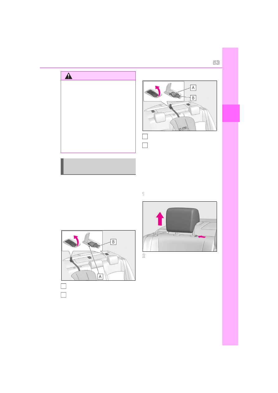
Anchor brackets (for top tether 
strap)

Anchor brackets are provided for each 
rear seat.
Use anchor brackets when fixing the 
top tether strap.

Outboard rear seats

Anchor brackets

Top tether strap

Rear center seat

Anchor bracket

Top tether strap

Fixing the top tether strap to the 
anchor bracket

Install the child restraint system in 
accordance to the operation manual 
enclosed with the child restraint sys-
tem.

1

Remove the head restraint.

2

Open the anchor bracket cover, 
latch the hook onto the anchor 
bracket and tighten the top tether 
strap.

Make sure the top tether strap is securely 
latched. (

P.50)

WARNING

When securing some types of child 

restraint systems in rear seats, it may 

not be possible to properly use the 

seat belts in positions next to the child 

restraint without interfering with it or 

affecting seat belt effectiveness. Be 

sure your seat belt fits snugly across 

your shoulder and low on your hips. If it 

does not, or if it interferes with the 

child restraint, move to a different 

position. Failure to do so may result in 

death or serious injury.

If the seat is adjusted, reconfirm the 

security of the child restraint system.

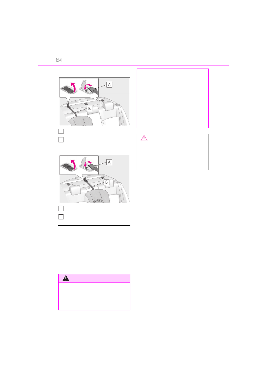
Using an anchor bracket (for top 
tether strap)

A

B

A

B
54

1-2. Child safety

Outboard rear seats

Hook

Top tether strap

Rear center seat

Hook

Top tether strap

Laws and regulations pertaining to 

anchors

The LATCH system conforms to 

FMVSS225 or CMVSS210.2. 

Child restraint systems conforming to 

FMVSS213 or CMVSS213 specifications 

can be used. 

This vehicle is designed to conform to SAE 

J1819.

WARNING

When installing a child restraint sys-

tem

Observe the following precautions. 

Failure to do so may result in death or 

serious injury.

A

B

A

B

Firmly attach the top tether strap and 

make sure that the belt is not twisted.

Do not attach the top tether strap to 

anything other than the anchor 

bracket.

After securing a child restraint system, 

never adjust the seat.

Follow all installation instructions pro-

vided by the child restraint system 

manufacturer.

NOTICE

Anchor brackets (for top tether 

strap)

When not in use, make certain to close 

the lid. If it remains open, the lid may be 

damaged.

55

1-3. Lexus Enform

1

For safety and security

1-3.Lexus Enform

“SOS” button

LED light indicators

Microphone

Subscribers have the following Safety 
Connect services available:

Automatic Collision Notification

*

Helps drivers receive necessary response 
from emergency service providers. 
(

P.56

)

*

: U.S. Patent No. 7,508,298 B2

Stolen Vehicle Location

Helps drivers in the event of vehicle theft. 
(

P.57

)

Emergency Assistance Button 
(“SOS”)

Connects drivers to response-center sup-
port. (

P.57

)

Enhanced Roadside Assistance

Provides drivers various on-road assis-
tance. (

P.57

)

After you have signed the Telematics 
Subscription Service Agreement and 
are enrolled, you can begin receiving 
services.
A variety of subscription terms is avail-
able for purchase. Contact your Lexus 
dealer, call the following or push the 
“SOS” button in your vehicle for fur-
ther subscription details.
• The United States

1-800-25-LEXUS (1-800-255-3987)

• Canada

1-800-26-LEXUS (1-800-265-3987)

• Puerto  Rico

Safety Connect

Safety Connect is a subscription-
based telematics service that uses 
Global Positioning System (GPS) 
data and embedded cellular tech-
nology to provide safety and secu-
rity features to subscribers. Safety 
Connect is supported by Lexus’ 
designated response center, which 
operates 24 hours per day, 7 days 
per week.

Safety Connect service is available 
by subscription on select, telemat-
ics hardware-equipped vehicles.

By using the Safety Connect ser-
vice, you are agreeing to be bound 
by the Connected Services Terms 
of Use, as in effect and amended 
from time to time, a current copy of 
which is available at Lexus.com. All 
use of the Safety Connect service is 
subject to such then-applicable 
Terms and Conditions.

System components

A
B

Services

Subscription

C

56

1-3. Lexus Enform

1-877-539-8777

Safety Connect Services Information

Phone calls using the vehicle’s 
Bluetooth

®

 technology will not be possi-

ble during Safety Connect.

Safety Connect is available beginning 

Fall 2009 on select Lexus models (in the 

contiguous United States only). Contact 

with the Safety Connect response center 

is dependent upon the telematics device 

being in operative condition, cellular con-

nection availability, and GPS satellite sig-

nal reception, which can limit the ability to 

reach the response center or receive 

emergency service support. Enrollment 

and Telematics Subscription Service 

Agreement required. A variety of sub-

scription terms is available; charges vary 

by subscription term selected and loca-

tion.

Automatic Collision Notification, Emer-

gency Assistance and Stolen Vehicle 

Location will function in the United 

States, including Hawaii and Alaska, 

Puerto Rico and in Canada, and 

Enhanced Roadside Assistance will func-

tion in the United States, Puerto Rico and 

in Canada.

Automatic Collision Notification, Emer-

gency Assistance, Stolen Vehicle and 

Enhanced Road Assistance will not func-

tion in the United States Virgin Islands.

For vehicles first sold in the USVI, no 

Safety Connect services will function in 

and outside the United States Virgin 

Islands.

Safety Connect services are not subject 

to section 255 of the Telecommunica-

tions Act and the device is not TTY com-

patible.

Languages

The Safety Connect response center will 

offer support in multiple languages. The 

Safety Connect system will offer voice 

prompts in English, Spanish, and French. 

Please indicate your language of choice 

when enrolling.

When contacting the response center

You may be unable to contact the response 

center if the network is busy.

When the power switch is turned to 
ON mode, the red indicator light 
comes on for 2 seconds then turns off. 
Afterward, the green indicator light 
comes on, indicating that the service is 
active.
The following indicator light patterns 
indicate specific system usage condi-
tions:

Green indicator light on = Active 
service

Green indicator light flashing = 
Safety Connect call in process

Red indicator light (except at vehi-
cle start-up) = System malfunction 
(contact your Lexus dealer)

No indicator light (off) = Safety 
Connect service not active

Automatic Collision Notification

In case of either airbag deployment or 
severe rear-end collision, the system is 
designed to automatically call the 
response center. The responding 
agent receives the vehicle’s location 
and attempts to speak with the vehicle 
occupants to assess the level of emer-
gency. If the occupants are unable to 
communicate, the agent automatically 
treats the call as an emergency, con-

Safety Connect LED light Indi-
cators

Safety Connect services

57

1-3. Lexus Enform

1

For safety and security

tacts the nearest emergency services 
provider to describe the situation, and 
requests that assistance be sent to the 
location.

Stolen Vehicle Location

If your vehicle is stolen, Safety Connect 
can work with local authorities to assist 
them in locating and recovering the 
vehicle. After filing a police report, call 
the Safety Connect response center at 
1-800-25-LEXUS (1-800-255-
3987) in the United States, 1-877-
539-8777 in Puerto Rico or 1-800-
265-3987 in Canada, and follow the 
prompts for Safety Connect to initiate 
this service.
In addition to assisting law enforce-
ment with recovery of a stolen vehicle, 
Safety-Connect-equipped vehicle 
location data may, under certain cir-
cumstances, be shared with third par-
ties to locate your vehicle. Further 
information is available at Lexus.com.

Emergency Assistance Button 
(“SOS”)

In the event of an emergency on the 
road, push the “SOS” button to reach 
the Safety Connect response center. 
The answering agent will determine 
your vehicle’s location, assess the 
emergency, and dispatch the neces-
sary assistance required.

If you accidentally press the “SOS” button, 
tell the response-center agent that you are 
not experiencing an emergency.

Enhanced Roadside Assistance

Enhanced Roadside Assistance adds 
GPS data to the already included war-

ranty-based Lexus roadside service.
Subscribers can press the “SOS” but-
ton to reach a Safety Connect 
response-center agent, who can help 
with a wide range of needs, such as: 
towing, flat tire, fuel delivery, etc. For a 
description of the Roadside Assistance 
services and their limitations, please 
see the Safety Connect Terms and 
Conditions, which are available at 
Lexus.com.

Important! Read this information about 
exposure to radio frequency signals 
before using Safety Connect;
The Safety Connect system installed in 
your vehicle is a low-power radio 
transmitter and receiver. It receives 
and also sends out radio frequency 
(RF) signals.
In August 1996, the Federal Commu-
nications Commission (FCC) adopted 
RF exposure guidelines with safety lev-
els for mobile wireless phones. Those 
guidelines are consistent with the 
safety standards previously set by the 
following U.S. and international stan-
dards bodies.

ANSI (American National Stan-
dards Institute) C95.1 [1992]

NCRP (National Council on Radia-
tion Protection and Measurement) 
Report 86 [1986]

ICNIRP (International Commission 
on Non-Ionizing Radiation Protec-

Safety information for Safety 
Connect

58

1-3. Lexus Enform

tion) [1996]

Those standards were based on com-
prehensive and periodic evaluations of 
the relevant scientific literature. Over 
120 scientists, engineers, and physi-
cians from universities, and govern-
ment health agencies and industries 
reviewed the available body of 
research to develop the ANSI Stan-
dard (C95.1).
The design of Safety Connect com-
plies with the FCC guidelines in addi-
tion to those standards.

Free/Open Source Software Informa-

tion

This product contains Free/Open Source 

Software (FOSS). The license information 

and/or the source code of such FOSS can 

be found at the following URL.
https://opensource.lge.com/osSch/

list?types=ALL&search=TL21BNU

59

1-4. Hybrid system

1

For safety and security

1-4.Hybrid system

The illustration is an example for explanation and may differ from the actual item.

Gasoline engine

Electric motor (traction motor)

When stopped/during start off

The gasoline engine stops

*

 when the 

vehicle is stopped. During start off, the 
electric motor (traction motor) drives 
the vehicle. At slow speeds or when 
traveling down a gentle slope, the 
engine is stopped

*

 and the electric 

motor (traction motor) is used.
When the shift lever is in N, the hybrid 
battery (traction battery) is not being 

charged.

*

: When the hybrid battery (traction bat-

tery) requires charging or the engine is 
warming up, etc., the gasoline engine will 
not automatically stop.

During normal driving

The gasoline engine is predominantly 
used. The electric motor (traction 
motor) charges the hybrid battery 
(traction battery) as necessary.

Hybrid system features

Your vehicle is a Hybrid Electric Vehicle. It has characteristics different from 
conventional vehicles. Be sure you are closely familiar with the characteristics 
of your vehicle, and operate it with care.
The hybrid system combines the use of a gasoline engine and an electric 
motor (traction motor) according to driving conditions, improving fuel effi-
ciency and reducing exhaust emissions.

System components

A
B

60

1-4. Hybrid system

When accelerating sharply

When the accelerator pedal is 
depressed heavily, the power of the 
hybrid battery (traction battery) is 
added to that of the gasoline engine via 
the electric motor (traction motor).

When braking (regenerative brak-
ing)

The wheels operate the electric motor 
(traction motor) as a power generator, 
and the hybrid battery (traction bat-
tery) is charged.

Regenerative braking

In the following situations, kinetic energy is 

converted to electric energy and decelera-

tion force can be obtained in conjunction 

with the recharging of the hybrid battery 

(traction battery).

The accelerator pedal is released while 

driving with the shift lever in D or S.

The brake pedal is depressed while driv-

ing with the shift lever in D or S.

EV indicator

The EV indicator comes on when the vehi-

cle is driven using only the electric motor 

(traction motor) or the gasoline engine is 

stopped.

Conditions in which the gasoline engine 

may not stop

The gasoline engine starts and stops auto-

matically. However, it may not stop auto-
matically in the following conditions

*

:

During gasoline engine warm-up

During hybrid battery (traction battery) 

charging

When the temperature of the hybrid bat-

tery (traction battery) is high or low

When the heater is switched on

*

: Depending on the circumstances, the 

gasoline engine may also not stop auto-
matically in other situations.

Charging the hybrid battery (traction 

battery)

As the gasoline engine charges the hybrid 

battery (traction battery), the battery does 

not need to be charged from an outside 

source. However, if the vehicle is left 

parked for a long time the hybrid battery 

(traction battery) will slowly discharge. For 

this reason, be sure to drive the vehicle at 

least once every few months for at least 30 

minutes or 10 miles (16 km). If the hybrid 

battery (traction battery) becomes fully dis-

charged and you are unable to start the 

hybrid system, contact your Lexus dealer.

Charging the 12-volt battery

P.389

After the 12-volt battery has discharged 

or when the terminal has been removed 

and installed during exchange, etc.

The gasoline engine may not stop even if 

the vehicle is being driven by the hybrid 

battery (traction battery). If this continues 

for a few days, contact your Lexus dealer.

Sounds and vibrations specific to a 

Hybrid Electric Vehicle

There may be no engine sound or vibration 

even though the vehicle is able to move with 

the “READY” indicator is illuminated. For 

safety, apply the parking brake and make 

sure to shift the shift lever to P when parked.
The following sounds or vibrations may 

occur when the hybrid system is operating 

and are not a malfunction:

Motor sounds may be heard from the 

engine compartment.

Sounds may be heard from the hybrid 

battery (traction battery) under the rear 

seats when the hybrid system starts or 

stops.

Relay operating sounds such as a snap or 

61

1-4. Hybrid system

1

For safety and security

soft clank will be emitted from the hybrid 

battery (traction battery), under the rear 

seats, when the hybrid system is started 

or stopped.

Sounds from the hybrid system may be 

heard when the trunk lid is open.

Sounds may be heard from the transmis-

sion when the gasoline engine starts or 

stops, when driving at low speeds, or 

during idling.

Engine sounds may be heard when 

accelerating sharply.

Sounds may be heard due to regenera-

tive braking when the brake pedal is 

depressed or as the accelerator pedal is 

released.

Vibration may be felt when the gasoline 

engine starts or stops.

Cooling fan sounds may be heard from 

the air intake vent under the rear seat.

Maintenance, repair, recycling, and dis-

posal

Contact your Lexus dealer regarding main-

tenance, repair, recycling and disposal. Do 

not dispose of the vehicle yourself.

Customization

Settings (e.g. on/off operation of the EV 

indicator) can be changed. 

(Customizable features: 

P.417)

When driving with the gasoline engine 
stopped, a sound, which changes in 
accordance with the driving speed, will 
be played in order to warn people 
nearby of the vehicle’s approach. This 
sound may be heard inside the vehicle. 
The sound will stop when the vehicle 
speed exceeds approximately 22 mph 
(35 km/h).

Acoustic Vehicle Alerting System

In the following cases, the Acoustic Vehicle 

Alerting System may be difficult for sur-

rounding people to hear.

In very noisy areas

In the wind or the rain

If “Acoustic Vehicle Alerting System 

Malfunction Visit your Dealer” is dis-

played on the multi-information display

The system may be malfunctioning. Have 

the vehicle inspected by your Lexus dealer.

Acoustic Vehicle Alerting Sys-
tem

62

1-4. Hybrid system

The illustration is an example for explanation and may differ from the actual item.

Warning label

Service plug

Hybrid battery (traction battery)

High voltage cables (orange)

Electric motor (traction motor)

Power control unit

Air conditioning compressor

Running out of fuel

When the vehicle has run out of fuel and the 

hybrid system cannot be started, refuel the 

vehicle with at least enough gasoline to 

make the low fuel level warning light 

(

P.363) go off. If there is only a small 

amount of fuel, the hybrid system may not 

be able to start. (The standard amount of 

fuel is about 2.4 gal. [9.0 L, 2.0 Imp.gal.], 

when the vehicle is on a level surface. This 

value may vary when the vehicle is on a 

slope. Add extra fuel when the vehicle is 

inclined.)

Electromagnetic waves

High voltage parts and cables on Hybrid 

Electric Vehicles incorporate electro-

Hybrid system precautions

Take care when handling the hybrid system, as it is a high voltage system 
(about 650 V at maximum) as well as contains parts that become extremely 
hot when the hybrid system is operating. Obey the warning labels attached to 
the vehicle.

System components

A
B
C
D

E
F

G

63

1-4. Hybrid system

1

For safety and security

magnetic shielding, and therefore emit 

approximately the same amount of elec-

tromagnetic waves as conventional gaso-

line powered vehicles or home electronic 

appliances.

Your vehicle may cause sound interfer-

ence in some third party-produced radio 

parts.

Hybrid battery (traction battery)

The hybrid battery (traction battery) has a 

limited service life. The lifespan of the 

hybrid battery (traction battery) can change 

in accordance with driving style and driving 

conditions.

Starting the hybrid system in an 

extremely cold environment (for vehi-

cles sold in except Canada)

When the hybrid battery (traction battery) 

is extremely cold (below approximately - 

22°F [-30°C]) under the influence of the 

outside temperature, it may not be possible 

to start the hybrid system. In this case, try to 

start the hybrid system again after the tem-

perature of the hybrid battery increases 

due to the outside temperature increase 

etc.

WARNING

High voltage precautions

This vehicle has high voltage DC and AC 

systems as well as a 12-volt system. DC 

and AC high voltage is very dangerous 

and can cause severe burns and electric 

shock that may result in death or serious 

injury.

Never touch, disassemble, remove or 

replace the high voltage parts, cables 

or their connectors.

The hybrid system will become hot 

after starting as the system uses high 

voltage. Be careful of both the high 

voltage and the high temperature, and 

always obey the warning labels 

attached to the vehicle.

Never try to open the service plug 

access hole located under the rear 

seat (right side). The service plug is 

used only when the vehicle is serviced 

and is subject to high voltage.

Road accident cautions

Observe the following precautions to 

reduce the risk of death or serious injury:

Pull your vehicle off the road, apply the 

parking brake, shift the shift lever to P, 

and turn the hybrid system off.

Do not touch the high voltage parts, 

cables and connectors.

If electric wires are exposed inside or 

outside your vehicle, an electric shock 

may occur. Never touch exposed 

electric wires.

If a fire occurs in the Hybrid Electric 

Vehicle, leave the vehicle as soon as 

possible. Never use a fire extinguisher 

that is not meant for electric fires. 

Using even a small amount of water 

may be dangerous.

If your vehicle needs to be towed, do 

so with front wheels raised. If the 

wheels connected to the electric 

motor (traction motor) are on the 

ground when towing, the motor may 

continue to generate electricity. This 

may cause a fire. (

P.357)

Carefully inspect the ground under the 

vehicle. If you find that liquid has 

leaked onto the ground, the fuel sys-

tem may have been damaged. Leave 

the vehicle as soon as possible.

64

1-4. Hybrid system

There is an air intake vent under the 
rear seat (right side) for the purpose of 
cooling the hybrid battery (traction 
battery). If the vent becomes blocked, 

WARNING

For vehicles sold in Canada: If a fluid 

leak occurs, do not touch the fluid as it 

may be strong alkaline electrolyte 

from the hybrid battery (traction bat-

tery). If it comes into contact with your 

skin or eyes, wash it off immediately 

with a large amount of water or, if pos-

sible, boric acid solution. Seek imme-

diate medical attention.

For vehicles sold in except Canada: 

Do not touch the battery if liquid is 

leaking from or adhering to it. If elec-

trolyte (carbonic-based organic elec-

trolyte) from the hybrid battery 

(traction battery) comes into contact 

with the eyes or skin, it could cause 

blindness or skin wounds. In the 

unlikely event that it comes into con-

tact with the eyes or skin, wash it off 

immediately with a large amount of 

water, and seek immediate medical 

attention.

For vehicles sold in except Canada: If 

electrolyte is leaking from the hybrid 

battery (traction battery), do not 

approach the vehicle. 

Even in the unlikely event that the 

hybrid battery (traction battery) is 

damaged, the internal construction of 

the battery will prevent a large amount 

of electrolyte from leaking out. How-

ever, any electrolyte that does leak out 

will give off a vapor. This vapor is an 

irritant to skin and eyes and could 

cause acute poisoning if inhaled.

For vehicles sold in except Canada: 

Do not bring burning or high-tem-

perature items close to the electrolyte. 

The electrolyte may ignite and cause a 

fire.

Hybrid battery (traction battery)

For vehicles sold in except Canada: 

Your vehicle contains a sealed lithium-

ion battery.

Never resell, hand over or modify the 

hybrid battery. To prevent accidents, 

hybrid batteries that have been 

removed from a disposed vehicle are 

collected through Lexus dealer. Do 

not dispose of the battery yourself. 

Unless the battery is properly col-

lected, the following may occur, result-

ing in death or serious injury:

• The hybrid battery may be illegally dis-

posed of or dumped, and it is hazard-

ous to the environment or someone 

may touch a high voltage part, result-

ing in an electric shock.

• The hybrid battery is intended to be 

used exclusively with your Hybrid 

Electric Vehicle. If the hybrid battery is 

used outside of your vehicle or modi-

fied in any way, accidents such as elec-

tric shock, heat generation, smoke 

generation, an explosion and electro-

lyte leakage may occur.

When reselling or handing over your 

vehicle, the possibility of an accident is 

extremely high because the person 

receiving the vehicle may not be aware 

of these dangers.

If your vehicle is disposed of without 

the hybrid battery having been 

removed, there is a danger of serious 

electric shock if high voltage parts, 

cables and their connectors are 

touched. In the event that your vehicle 

must be disposed of, the hybrid battery 

must be disposed of by your Lexus 

dealer or a qualified service shop. If the 

hybrid battery is not disposed of prop-

erly, it may cause electric shock that 

can result in death or serious injury.

Hybrid battery (traction battery) 
air intake vent

65

1-4. Hybrid system

1

For safety and security

the hybrid battery (traction battery) 
may overheat, leading to a reduction in 
the hybrid battery (traction battery) 
output.

When a certain level of impact is 
detected by the impact sensor, the 
emergency shut off system blocks the 
high voltage current and stops the fuel 
pump to minimize the risk of electrocu-
tion and fuel leakage. If the emergency 
shut off system activates, your vehicle 
will not restart. To restart the hybrid 
system, contact your Lexus dealer.

A message is automatically displayed 
when a malfunction occurs in the 
hybrid system or an improper opera-
tion is attempted.
If a warning message is shown on the 
multi-information display, read the 
message and follow the instructions.

NOTICE

Hybrid battery (traction battery) air 

intake vent

Make sure not to block the air intake 

vent with anything, such as a seat 

cover, plastic cover, or luggage. If the 

vents become blocked, the hybrid bat-

tery (traction battery) input and output 

may be restricted, leading to a reduc-

tion in hybrid battery (traction battery) 

output and a malfunction.

When dust etc. has accumulated in the 

air intake vent, periodically clean it 

with a vacuum cleaner to prevent the 

vent from clogging.

Do not get water or foreign materials 

in the air intake vent as this may cause 

a short circuit and damage the hybrid 

battery (traction battery).

Do not carry large amounts of water 

such as water cooler bottles in the 

vehicle. If water spills onto the hybrid 

battery (traction battery), the battery 

may be damaged. Have the vehicle 

inspected by your Lexus dealer.

There is a filter installed to the air 

intake vent. When the filter remains 

noticeably dirty even after cleaning the 

air intake vent, filter cleaning or 

replacement is recommended. For 

information regarding filter cleaning or 

replacement, refer to P.340.

If “Maintenance required for Traction 

battery cooling parts See owner’s 

manual” is shown on the multi-infor-

mation display, the air intake vent and 

filter may be clogged. Refer to P.340 

for information on how to clean the air 

intake vent.

Emergency shut off system

Hybrid warning message

66

1-4. Hybrid system

If a warning light comes on, a warning 

message is displayed, or the 12-volt bat-

tery is disconnected

The hybrid system may not start. In this 

case, try to start the system again. If the 

“READY” indicator does not come on, con-

tact your Lexus dealer.

67

1-5. Theft deterrent system

1

For safety and security

1-5.Theft deterrent system

The indicator light flashes after the 
power switch has been turned off to 
indicate that the system is operating.
The indicator light stops flashing after 
the power switch has been turned to 
ACCESSORY or ON mode to indi-
cate that the system has been can-
celed.

System maintenance

The vehicle has a maintenance-free type 

immobilizer system.

Conditions that may cause the system to 

malfunction

If the grip portion of the key is in contact 

with a metallic object

If the key is in close proximity to or touch-

ing a key registered to the security sys-

tem (key with a built-in transponder chip) 

of another vehicle

Immobilizer system

The vehicle’s keys have built-in 
transponder chips that prevent the 
hybrid system from starting if a key 
has not been previously registered 
in the vehicle’s on-board computer.
Never leave the keys inside the 
vehicle when you leave the vehicle.

This system is designed to help pre-
vent vehicle theft but does not guar-
antee absolute security against all 
vehicle thefts.

Operating the system

NOTICE

To ensure the system operates cor-

rectly

Do not modify or remove the system. If 

modified or removed, the proper opera-

tion of the system cannot be guaranteed.

68

1-5. Theft deterrent system

Items to check before locking the 
vehicle

To prevent unexpected triggering of 
the alarm and vehicle theft, make sure 
of the following:

Nobody is in the vehicle.

The windows and moon roof are 
closed before the alarm is set.

No valuables or other personal 
items are left in the vehicle.

Setting

Close the doors, trunk and hood, and 
lock all the doors using the entry func-

tion or wireless remote control. The 
system will be set automatically after 
30 seconds.
Except for Canada, the alarm can also 
be set using the mechanical key.

The indicator light changes from being on 
to flashing when the system is set.

Canceling or stopping

Do one of the following to deactivate 
or stop the alarm:

Except for Canada: Unlock the 
doors using the entry function, wire-
less remote control or mechanical 
key.

For Canada: Unlock the doors using 
the entry function or wireless 
remote control.

Turn the power switch to ACCES-
SORY or ON mode, or start the 
hybrid system. (The alarm will be 
deactivated or stopped after a few 
seconds.)

System maintenance

The vehicle has a maintenance-free type 

alarm system.

Triggering of the alarm

The alarm may be triggered in the following 

situations: 

(Stopping the alarm deactivates the alarm 

system.)

Alarm

The alarm uses light and sound to 
give an alert when an intrusion is 
detected. 
The alarm is triggered in the follow-
ing situations when the alarm is set:

A locked door is unlocked or 
opened in any way other than 
using the entry function, wireless 
remote control or mechanical 
key

*

. (The doors will lock again 

automatically.)

A locked trunk is unlocked or 
opened in any way other than 
using the entry function or wire-
less remote control.

The hood is opened.

*

: Except  for  Canada

Setting/canceling/stopping the 
alarm system

69

1-5. Theft deterrent system

1

For safety and security

For Canada: The doors are unlocked 

using the mechanical key.

The trunk is unlocked using the mechani-

cal key.

A person inside the vehicle opens a door, 

the trunk or hood, or unlocks the vehicle 

using a door lock switch.

The 12-volt battery is recharged or 

replaced when the vehicle is locked. 

(

P.389)

Alarm-operated door lock

In the following cases, depending on the sit-

uation, the door may automatically lock to 

prevent improper entry into the vehicle:

When a person remaining in the vehicle 

unlocks the door and the alarm is acti-

vated.

While the alarm is activated, a person 

remaining in the vehicle unlocks the door.

When recharging or replacing the 12-

volt battery

NOTICE

To ensure the system operates cor-

rectly

Do not modify or remove the system. If 

modified or removed, the proper opera-

tion of the system cannot be guaranteed.

70

1-5. Theft deterrent system

71

2

2

Vehi

cle

 status 

inform

ati

on a

nd i

ndic
ators

Vehicle status information

and indicators

2-1. Instrument cluster

Warning lights and indicators..

72

Gauges and meters (except F 

SPORT models) ........................

76

Gauges and meters (F SPORT 

models)..........................................

80

Multi-information display..........

85

Head-up display ............................

91

Energy monitor/consumption 

screen ............................................

95

72

2-1. Instrument cluster

2-1.Instrument cluster

Except F SPORT models

The image may differ from the actual condition.

F SPORT models

The image may differ from the actual condition.

Warning lights and indicators

The warning lights and indicators on the instrument cluster, center panel and 
outside rear view mirrors inform the driver of the status of the vehicle’s vari-
ous systems.

Warning lights and indicators displayed on the instrument cluster

73

2-1. Instrument cluster

2

Vehi

cle

 status 

inform

ati

on a

nd i

ndic
ators

Warning lights inform the driver of 
malfunctions in the indicated vehicle’s 
systems.

Warning lights

(U.S.A.)

Brake system warning light

*1


(

P.360)

(red)

(Canada)

Brake system warning light

*1


(

P.360)

(yellow)

Brake system warning light

*1


(

P.360)

High coolant temperature 
warning light

*2

 (

P.360)

Charging system warning 
light

*2

 (

P.361)

Low engine oil pressure warn-
ing light

*2

 (

P.361)

(U.S.A.)

Malfunction indicator lamp

*1


(

P.361)

(Canada)

Malfunction indicator lamp

*1


(

P.361)

SRS warning light

*1

 (

P.361)

(U.S.A.)

ABS warning light

*1

 (

P.362)

(Canada)

ABS warning light

*1

 (

P.362)

Inappropriate pedal operation 
warning light

*2

 (

P.362)

(red)

Electric power steering system 
warning light

*1

 (

P.362)

(yellow)

Electric power steering system 
warning light

*1

 (

P.362)

Low fuel level warning light 
(

P.363)

Driver’s and front passenger’s 
seat belt reminder light 
(

P.363)

Rear passengers’ seat belt 
reminder lights

*2

 (

P.363)

Tire pressure warning light

*1


(

P.364)

(orange)

LTA indicator

*2

 (

P.364)

(flashes)

Intuitive parking assist OFF indi-
cator

*1

 (if equipped) (

P.364)

(flashes)

RCTA OFF indicator

*1


(

P.365)

(flashes or 

illuminates)

RCD OFF indicator (if 
equipped) (

P.365)

(flashes)

PKSB OFF indicator

*1

 (if 

equipped) (

P.365)

(flashes or 

illuminates)

PCS warning light

*1

 (

P.366)

Slip indicator

*1

 (

P.366)

(flashes)

(U.S.A.)

Parking brake indicator 
(

P.366)

(flashes)

(Canada)

Parking brake indicator 
(

P.366)

74

2-1. Instrument cluster

*1

: These lights come on when the power 

switch is turned to ON mode to indi-
cate that a system check is being per-
formed. They will turn off after the 
hybrid system is on, or after a few sec-
onds. There may be a malfunction in a 
system if the lights do not come on, or 
turn off. Have the vehicle inspected by 
your Lexus dealer.

*2

: This light illuminates on the multi-infor-

mation display.

The indicators inform the driver of the 
operating state of the vehicle’s various 
systems.

(flashes)

Brake hold operated indica-
tor

*1

 (

P.367)

Hybrid system overheat warn-
ing light

*2

(

P.367)

Master warning light

*1


(

P.367)

WARNING

If a safety system warning light does 

not come on

Should a safety system light such as the 

ABS and SRS warning light not come on 

when you start the hybrid system, this 

could mean that these systems are not 

available to help protect you in an acci-

dent, which could result in death or seri-

ous injury. Have the vehicle inspected by 

your Lexus dealer immediately if this 

occurs.

Indicators

Turn signal indicator (

P.158)

(U.S.A.)

Headlight indicator (

P.163)

(Canada)

Tail light indicator (

P.163)

Headlight high beam indicator 
(

P.165)

Automatic High Beam indicator 
(

P.166)

PCS warning light

*1, 2

 (

P.181)

Cruise control indicator

*3


(

P.203)

Dynamic radar cruise control 
indicator

*3

 (

P.203)

Cruise control “SET” indica-
tor

*3

 (

P.203)

(white)

LTA indicator

*3

 (

P.196)

(green)

LTA indicator

*3

 (

P.181, 196)

(orange)

(flashes)

LTA indicator

*3

 (

P.196)

BSM outside rear view mirror 
indicators

*1, 4

 (

P.213, 229)

BSM indicator (

P.213)

Intuitive parking assist OFF indi-
cator

*1, 2

 (if equipped) 

(

P.222)

RCTA OFF indicator

*1, 2


(

P.230)

RCD OFF indicator

*2

 (if 

equipped) (

P.235)

PKSB OFF indicator

*1, 2

 (if 

equipped) (

P.240)

(flashes)

Slip indicator

*1

 (

P.253)

75

2-1. Instrument cluster

2

Vehi

cle

 status 

inform

ati

on a

nd i

ndic
ators

Drive mode indicators

Except F SPORT models

F SPORT models

*1

: These lights come on when the power 

switch is turned to ON mode to indi-
cate that a system check is being per-
formed. They will turn off after the 
hybrid system is on, or after a few sec-
onds. There may be a malfunction in a 
system if the lights do not come on, or 
turn off. Have the vehicle inspected by 
your Lexus dealer.

*2

: This light comes on when the system is 

turned off.

*3

: This light illuminates on the multi-infor-

mation display.

*4

: This light illuminates on the outside rear 

view mirrors.

*5

: Except F SPORT models: This light illu-

minates on the multi-information dis-
play.

*6

: When the outside temperature is 

approximately 37°F (3°C) or lower, 
this indicator will flash for approxi-
mately 10 seconds, then stay on.

*7

: This light illuminates on the center 

panel.

VSC OFF indicator

*1, 2


(

P.253)

Smart access system with push-
button start indicator

*3


(

P.148)

“READY” indicator (

P.148)

AGC indicator

*3

 (

P.219)

EV drive mode indicator 
(

P.153)

(U.S.A.)

Parking brake indicator 
(

P.159)

(Canada)

Parking brake indicator 
(

P.159)

Brake hold standby indicator

*1


(

P.161)

Brake hold operated indica-
tor

*1

 (

P.161)

EV indicator

*5

 (

P.60)

Low outside temperature indi-
cator

*3, 6

 (

P.76, 80)

“PASSENGER AIR 
BAG” indicator lights

*1, 7


(

P.37)

Traction battery status indica-
tor (if equipped)

*3

 (

P.95)

Eco drive mode indicator 
(

P.218)

Sport mode indicator (

P.218)

Custom mode indicator (if 
equipped) (

P.218)

Eco drive mode indicator 
(

P.218)

Sport mode indicator (if 
equipped) (

P.218)

Sport S mode indicator (if 
equipped) (

P.218)

Sport S+ mode indicator (if 
equipped) (

P.218)

76

2-1. Instrument cluster

Locations of gauges and meters

The units of measure may differ depending on the intended destination of the vehicle.

Multi-information display

Presents the driver with a variety of vehicle data (

P.85)

Displays warning messages if a malfunction occurs (

P.370)

Outside temperature

Displays the outside temperature within the range of -40°F (-40°C) to 122°F (50°C)
Low outside temperature indicator comes on when the ambient temperature is 37°F 
(3°C) or lower

Hybrid System Indicator

Displays hybrid system output or regeneration level (

P.77)

This display changes to a tachometer depending on the driving mode, and can be set to 
show the tachometer in any driving mode on the settings display. (

P.89, 218)

Speedometer

Clock

Time displayed is linked to the analog clock on the center panel. (

P.283)

Engine coolant temperature gauge

Displays the engine coolant temperature

Fuel gauge

Displays the quantity of fuel remaining in the tank

Gauges and meters (except F SPORT models)

Meter display

A

B

C

D

E

F

G

77

2-1. Instrument cluster

2

Vehi

cle

 status 

inform

ati

on a

nd i

ndic
ators

In the following situations, the actual quantity of fuel remaining in the tank may not be dis-
played correctly. Refer to P.77 if the actual quantity of fuel remaining in the tank is not dis-
played correctly.
• A small amount of fuel is added.
• Fuel is added with the fuel gauge near or at “F”.
• The vehicle is stopped on an uneven surface, such as a slope.
• The vehicle is driven on a slope or around a curve.

Shift position and shift range (

P.154)

Odometer and trip meter display (

P.78)

Hybrid System Indicator

Charge area

Shows regeneration

*

 status.

Regenerated energy will be used to 
charge the hybrid battery (traction bat-
tery).

Hybrid Eco area

Shows that gasoline engine power is not 
being used very often.
The gasoline engine will automatically stop 
and restart under various conditions.

Eco area

Shows that the vehicle is being driven in an 
Eco-friendly manner.
By keeping the bar display within Eco area, 
more Eco-friendly driving can be 
achieved.

Power area

Shows that an Eco-friendly driving range is 
being exceeded (during full power driving 
etc.)

*

: When used in this manual, regeneration 

refers to the conversion of energy cre-
ated by the movement of the vehicle into 
electrical energy.

Engine speed

On Hybrid Electric Vehicles, engine speed 

is precisely controlled in order to help 

improve fuel efficiency and reduce exhaust 

emissions etc.

There are times when the engine speed that 

is displayed may differ even when vehicle 

operation and driving conditions are the 

same.

Hybrid System Indicator is displayed 

when

The Hybrid System Indicator is displayed in 

the following situations:

The shift lever is in D or S.

The hybrid system is started.

Manually updating the fuel gauge and 

possible driving range

The fuel gauge and the possible driving 

range are linked. If the displays of the fuel 

gauge and possible driving range do not 

update after adding a small amount of fuel, 

the displays can be updated by performing 

the following procedure.

1

Stop the vehicle on a level surface.

2

Press the “ODO TRIP” switch to 

change the odometer and trip meter 

display to odometer.

3

Turn the power switch off.

4

While pressing and holding the “ODO 

TRIP” switch, turn the power switch to 

ON mode.

H

I

A

B

C

D

78

2-1. Instrument cluster

5

Continue to hold the “ODO TRIP” 

switch for approximately 5 seconds, 

and then release it once the odometer 

begins flashing.

Updating is complete once the odometer 

flashes for approximately 5 seconds and 

then the display returns to normal.

Outside temperature display

In the following situations, the correct 

outside temperature may not be dis-

played, or the display may take longer 

than normal to change:

• When stopped, or driving at low speeds 

(less than 12 mph [20 km/h])

• When the outside temperature has 

changed suddenly (at the entrance/exit 

of a garage, tunnel, etc.)

When “--” or “E” is displayed, the system 

may be malfunctioning. Take your vehicle 

to your Lexus dealer.

Liquid crystal display

P.86

Customization

The gauges and meters can be customized 
on 

 of the multi-information display. 

(

P.89)

Display items

Odometer

Displays the total distance the vehicle has 
been driven.

Trip meter A/trip meter B

Displays the distance the vehicle has been 
driven since the meter was last reset. Trip 
meters A and B can be used to record and 
display different distances independently.

Distance until next engine oil 
change

Displays the distance the vehicle can be 
driven until an oil change is necessary.

Changing the display

Each time the “ODO TRIP” switch is 
pressed, the displayed item will be 
changed. When the trip meter is dis-
played, pressing and holding the switch 
will reset the trip meter.

WARNING

The information display at low tem-

peratures

Allow the interior of the vehicle to warm 

up before using the liquid crystal infor-

mation display. At extremely low tem-

peratures, the information display 

monitor may respond slowly, and display 

changes may be delayed.

For example, there is a lag between the 

driver’s shifting and the new gear num-

ber appearing on the display. This lag 

could cause the driver to downshift 

again, causing rapid and excessive 

engine braking and possibly an accident 

resulting in death or injury.

NOTICE

To prevent damage to the engine and 

its components

Do not let the indicator needle of the 

tachometer enter the red zone, which 

indicates the maximum engine speed.

The engine may be overheating if the 

engine coolant temperature gauge is 

in the red zone (H). In this case, imme-

diately stop the vehicle in a safe place, 

and check the engine after it has 

cooled completely. (

P.391)

Odometer and trip meter dis-
play

79

2-1. Instrument cluster

2

Vehi

cle

 status 

inform

ati

on a

nd i

ndic
ators

Pop-up display

Distance until the next engine oil 
change will be displayed when a warn-
ing message indicating that oil mainte-
nance should be performed soon or is 
required is displayed.

The brightness of the instrument panel 
lights can be adjusted.

1

Darker

2

Brighter

Brightness of the meter lights (day mode 

and night mode)

The brightness of the meter lights can be 

adjusted individually.
In the following situations, the meters 

changes between day mode and night 

mode.

Day mode: When the tail lights are off or 

when the tail lights are on but the sur-

rounding area is bright

Night mode: When the tail lights are on 

and the surrounding area is dark

Changing the instrument panel 
light brightness

80

2-1. Instrument cluster

Locations of gauges and meters

When the main meter is moved to the right, some of the meter displays and the 
gauge layout will change. (

P.85)

Main meter in center position

The units of measure may differ depending on the intended destination of the vehicle.

Odometer and trip meter display (

P.84)

Engine coolant temperature gauge

Displays the engine coolant temperature

Outside temperature

Displays the outside temperature within the range of -40°F (-40°C) to 122°F (50°C)
Low outside temperature indicator comes on when the ambient temperature is 37°F 
(3°C) or lower

Hybrid System Indicator

Displays hybrid system output or regeneration level (

P.82)

This display changes to a tachometer depending on the driving mode, and can be set to 
show the tachometer in any driving mode on the settings display. (

P.89, 218)

• Rev indicator (

P.82)

• Rev  peak  (

P.83)

Speedometer

Shift position and shift range (

P.154)

Gauges and meters (F SPORT models)

Meter display

A
B

C

D

E
F

81

2-1. Instrument cluster

2

Vehi

cle

 status 

inform

ati

on a

nd i

ndic
ators

Clock

Time displayed is linked to the analog clock on the center panel. (

P.283)

Fuel gauge

Displays the quantity of fuel remaining in the tank
In the following situations, the actual quantity of fuel remaining in the tank may not be dis-
played correctly. Refer to P.83 if the actual quantity of fuel remaining in the tank is not dis-
played correctly.
• A small amount of fuel is added.
• Fuel is added with the fuel gauge near or at “F”.
• The vehicle is stopped on an uneven surface, such as a slope.
• The vehicle is driven on a slope or around a curve.

Multi-information display

Presents the driver with a variety of vehicle data (

P.85)

Displays warning messages if a malfunction occurs (

P.370)

Main meter moved to the right

The units of measure may differ depending on the intended destination of the vehicle.

Outside temperature

Displays the outside temperature within the range of -40°F (-40°C) to 122°F (50°C)
Low outside temperature indicator comes on when the ambient temperature is 37°F 
(3°C) or lower

Clock

Time displayed is linked to the analog clock on the center panel. (

P.283)

Hybrid System Indicator

Displays hybrid system output or regeneration level (

P.82)

This display changes to a tachometer depending on the driving mode, and can be set to 
show the tachometer in any driving mode on the settings display. (

P.89, 218)

G

H

I

A

B

C

82

2-1. Instrument cluster

• Rev indicator (

P.82)

• Rev  peak  (

P.83)

Speedometer

Shift position and shift range (

P.154)

Odometer and trip meter display (

P.84)

Fuel gauge

Displays the quantity of fuel remaining in the tank
In the following situations, the actual quantity of fuel remaining in the tank may not be dis-
played correctly. Refer to P.83 if the actual quantity of fuel remaining in the tank is not dis-
played correctly.
• A small amount of fuel is added.
• Fuel is added with the fuel gauge near or at “F”.
• The vehicle is stopped on an uneven surface, such as a slope.
• The vehicle is driven on a slope or around a curve.

Engine coolant temperature gauge

Displays the engine coolant temperature

Multi-information display

Presents the driver with a variety of vehicle data (

P.85)

Displays warning messages if a malfunction occurs (

P.370)

Hybrid System Indicator

Charge area

Shows regeneration

*

 status.

Regenerated energy will be used to 
charge the hybrid battery (traction bat-
tery).

Hybrid Eco area

Shows that gasoline engine power is not 
being used very often.
The gasoline engine will automatically stop 

and restart under various conditions.

Eco area

Shows that the vehicle is being driven in an 
Eco-friendly manner.
By keeping the bar display within Eco area, 
more Eco-friendly driving can be 
achieved.

Power area

Shows that an Eco-friendly driving range is 
being exceeded (during full power driving 
etc.)

*

: When used in this manual, regeneration 

refers to the conversion of energy cre-
ated by the movement of the vehicle into 
electrical energy.

Rev indicator

When the engine speed reaches a set 
speed or the red zone, a ring-shaped 

D

E
F

G

H

I

A

B

C

D

83

2-1. Instrument cluster

2

Vehi

cle

 status 

inform

ati

on a

nd i

ndic
ators

indicator (

) will be displayed on the 

tachometer.

The indicators will be displayed in amber 
when the engine speed reaches a set 
speed, and in red when the engine speed 
reaches the red zone.
The engine speed at which the rev indica-
tor will begin to be displayed can be set on 

 of the multi-information display. 

(

P.89)

Rev peak

When the engine speed reaches or 
exceeds 4000 r/min, an afterimage of 
the tachometer will be displayed at the 
highest engine speed for approxi-
mately 1 second.

Engine speed

On Hybrid Electric Vehicles, engine speed 

is precisely controlled in order to help 

improve fuel efficiency and reduce exhaust 

emissions etc.

There are times when the engine speed that 

is displayed may differ even when vehicle 

operation and driving conditions are the 

same.

Hybrid System Indicator is displayed 

when

The Hybrid System Indicator is displayed in 

the following situations:

The shift lever is in D or S.

The hybrid system is started.

Manually updating the fuel gauge and 

possible driving range

The fuel gauge and the possible driving 

range are linked. If the displays of the fuel 

gauge and possible driving range do not 

update after adding a small amount of fuel, 

the displays can be updated by performing 

the following procedure.

1

Stop the vehicle on a level surface.

2

Press the “ODO TRIP” switch to 

change the odometer and trip meter 

display to odometer.

3

Turn the power switch off.

4

While pressing and holding the “ODO 

TRIP” switch, turn the power switch to 

ON mode.

5

Continue to hold the “ODO TRIP” 

switch for approximately 5 seconds, 

and then release it once the odometer 

begins flashing.

Updating is complete once the odometer 

flashes for approximately 5 seconds and 

then the display returns to normal.

Outside temperature display

In the following situations, the correct 

outside temperature may not be dis-

played, or the display may take longer 

than normal to change:

• When stopped, or driving at low speeds 

(less than 12 mph [20 km/h])

• When the outside temperature has 

changed suddenly (at the entrance/exit 

of a garage, tunnel, etc.)

When “--” or “E” is displayed, the system 

may be malfunctioning. Take your vehicle 

to your Lexus dealer.

Liquid crystal display

P.86

A

84

2-1. Instrument cluster

Customization

The gauges and meters can be customized 
on 

 of the multi-information display. 

(

P.89)

Display items

Odometer

Displays the total distance the vehicle has 
been driven.

Trip meter A/trip meter B

Displays the distance the vehicle has been 
driven since the meter was last reset. Trip 
meters A and B can be used to record and 
display different distances independently.

Distance until next engine oil 
change

Displays the distance the vehicle can be 
driven until an oil change is necessary.

Changing the display

Each time the “ODO TRIP” switch is 
pressed, the displayed item will be 
changed. When the trip meter is dis-
played, pressing and holding the switch 
will reset the trip meter.

Pop-up display

Distance until the next engine oil 
change will be displayed when a warn-
ing message indicating that oil mainte-
nance should be performed soon or is 
required is displayed.

The brightness of the instrument panel 
lights can be adjusted.

WARNING

The information display at low tem-

peratures

Allow the interior of the vehicle to warm 

up before using the liquid crystal infor-

mation display. At extremely low tem-

peratures, the information display 

monitor may respond slowly, and display 

changes may be delayed.

For example, there is a lag between the 

driver’s shifting and the new gear num-

ber appearing on the display. This lag 

could cause the driver to downshift 

again, causing rapid and excessive 

engine braking and possibly an accident 

resulting in death or injury.

NOTICE

To prevent damage to the engine and 

its components

Do not let the indicator needle of the 

tachometer enter the red zone, which 

indicates the maximum engine speed.

The engine may be overheating if the 

engine coolant temperature gauge is 

in the red zone (H). In this case, imme-

diately stop the vehicle in a safe place, 

and check the engine after it has 

cooled completely. (

P.391)

Odometer and trip meter dis-
play

Changing the instrument panel 
light brightness


Content      ..      1      2      3      ..