Lexus RX (2023 year). Manual in english - page 2
 

  Index      Manuals     Lexus RX (2023 year). Manual in english


Search            copyright infringement  


Content      ..      1      2      3      ..


Lexus RX (2023 year). Manual in english - page 2


61

1

1-2. Child safety

For safety and security

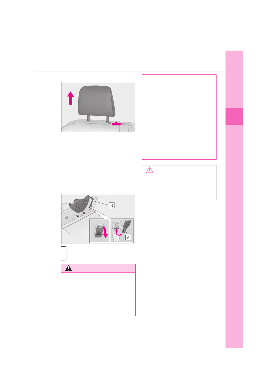
raise it to the uppermost position.

2

Open the top tether anchorage 
cover, latch the hook onto the top 
tether anchorage and tighten the 
top strap.

Make sure the top strap is securely latched. 

(

P.59)

When installing the child restraint system 

with the head restraint being raised, be 

sure to have the top strap pass underneath 

the head restraint.

Hook
Top strap

WARNING

When installing a child restraint sys-

tem

Observe the following precautions.

Failure to do so may result in death or 

serious injury.

Firmly attach the top strap and make 

sure that the belt is not twisted.

A
B

Do not attach the top strap to anything 

other than the top tether anchorage of 

the seat the child restraint system is 

installed to.

After securing a child restraint system, 

never adjust the seat.

Follow all installation instructions pro-

vided by the child restraint system 

manufacturer.

When installing the child restraint sys-

tem with the head restraint being 

raised, after the head restraint has 

been raised and then the top tether 

anchorage has been fixed, do not 

lower the head restraint.

NOTICE

Top tether anchorages

When not in use, make certain to close 

the lid. If it remains open, the lid may be 

damaged.

62

1-2. Child safety

Points to remember: P.62
Child restraint system: P.63
When using a child restraint system: 
P.65
Child restraint system installation 
method
• Fixed with a seat belt: P.68
• Fixed with an ISOFIX rigid anchor: 

P.72

• Using an anchor bracket (for top 

strap): P.76

If child restraint system regulations 
exist in the country where you 
reside, please contact your Lexus 

dealer for the child restraint system 
installation.

Use a child restraint system until the 
child becomes large enough to 
properly wear the vehicle’s seat belt.

Choose a child restraint system 
appropriate to the age and size of 
the child.

Note that not all child restraint sys-
tems can fit in all vehicles.
Before using or purchasing a child 
restraint system, check the compati-
bility of the child restraint system 
with seat positions. (

P.68, 72)

Child restraint systems (for 
India)

Before installing a child restraint 
system in the vehicle, there are pre-
cautions that need to be observed, 
different types of child restraint sys-
tems, as well as installation meth-
ods, etc., written in this manual.

Use a child restraint system when 
riding with a small child that cannot 
properly use a seat belt. For the 
child’s safety, install the child restraint 
system to a rear seat. Be sure to fol-
low the installation method that is in 
the operation manual enclosed with 
the restraint system.

Table of contents

Points to remember

WARNING

When a child is riding

Observe the following precautions.

Failure to do so may result in death or 

serious injury.

For effective protection in automobile 

accidents and sudden stops, a child 

must be properly restrained, using a 

seat belt or child restraint system 

which is correctly installed. For installa-

tion details, refer to the operation man-

ual enclosed with the child restraint 

system. General installation instruction 

is provided in this manual.

Lexus strongly urges the use of a 

proper child restraint system that con-

forms to the weight and size of the 

child, installed on the rear seat. 

According to accident statistics, the 

child is safer when properly restrained 

in the rear seat than in the front seat.

Holding a child in your or someone 

else’s arms is not a substitute for a child 

restraint system. In an accident, the 

child can be crushed against the wind-

shield or between the holder and the 

interior of the vehicle.

63

1

1-2. Child safety

For safety and security

Install the available child restraint system in vehicle upon confirming the following 
items.

Standards for child restraint sys-
tems

Use a child restraint system that con-
forms to ECE R44

*1

 or ECE R129

*1, 2

.

The following approval mark is dis-
played on child restraint systems which 
are conformed.
Check for an approval mark attached 
to the child restraint system.

WARNING

Handling the child restraint system

If the child restraint system is not prop-

erly fixed in place, the child or other pas-

sengers may be seriously injured or even 

killed in the event of sudden braking, sud-

den swerving, or an accident.

If the vehicle were to receive a strong 

impact from an accident, etc., it is pos-

sible that the child restraint system has 

damage that is not readily visible. In 

such cases, do not reuse the restraint 

system.

Depending on the child restraint sys-

tem, installation may be difficult or 

impossible. In those cases, check 

whether the child restraint system is 

suitable for installment in the vehicle. 

(

P.68, 72) Be sure to install and 

observe the usage rules after carefully 

reading the child restraint system fixing 

method in this manual, as well as the 

operation manual enclosed with the 

child restraint system.

Keep the child restraint system prop-

erly secured on the seat even if it is not 

in use. Do not store the child restraint 

system unsecured in the passenger 

compartment.

If it is necessary to detach the child 

restraint system, remove it from the 

vehicle or store it securely in the lug-

gage compartment.

Child restraint system

64

1-2. Child safety

Example of the displayed regulation num-
ber

ECE R44 approval mark

*3

The weight range of the child who is 
applicable for an ECE R44 
approval mark is indicated.

ECE R129 approval mark

*3

The height range of the child who is 
applicable as well as available 
weights for an ECE R129 approval 
mark is indicated.

*1

: ECE R44 and ECE R129 are U.N. reg-

ulations for child restraint systems.

*2

: The child restraint systems mentioned in 

the table may not be available outside of 
the EU area.

*3

: The displayed mark may differ depend-

ing on the product.

Mass group (ECE R44 only)

This Mass group table is required when confirming the child restraint system com-
patibility. Confirm in accordance with the child restraint system compatibility table. 
(

P.68, 72)

The child restraint system which conforms to the standard of ECE R44 is catego-
rized into 5 groups according to the weight of the child.

*

: The age range is a standard approximation. Choose according to the weight of the child.

Types of child restraint system installation methods

Confirm with the operation manual enclosed with the child restraint system about 
the installation of the child restraint system.

A

B

Mass group

Child weight

Reference age

*

Group 0

until 10 kg (22 lb.)

about 9 months

Group 0+

until 13 kg (28 lb.)

about 1.5 years

Group I

9 - 18 kg (20 to 39 lb.)

from 9 months - about 4 years

Group II

15 - 25 kg (34 to 55 lb.)

from 3 years - about 7 years

Group III

22 - 36 kg (49 to 79 lb.)

from 6 years - about 12 years

65

1

1-2. Child safety

For safety and security

When installing a child restraint 
system to a front passenger seat

For the safety of a child, install child 
restraint systems to a rear seats. When 
installing child restraint system to a 
front passenger seat is unavoidable, 
adjust the seat as follows and install the 

child restraint system.

Move the seat fully rearward.

Move the seat height to the upper 
most position.

Adjust the seatback angle to the 
most upright position.

When installing a forward-facing child 
seat, if there is a gap between the child seat 
and the seatback, adjust the seatback 
angle until good contact is achieved.

Installation method

Page

Seat belt attachment

P.68

ISOFIX rigid anchor attach-

ment

P.72

Anchor brackets (for top 

strap) attachment

P.76

When using a child restraint sys-
tem

66

1-2. Child safety

If the head restraint interferes with 
your child restraint system, and the 
head restraint can be removed, 
remove the head restraint.

Otherwise, put the head restraint in the 
upper most position.

WARNING

When using a child restraint system

Observe the following precautions.

Failure to do so may result in death or 

serious injury.

Never use a rear-facing child restraint 

system on the front passenger seat.

The force of the rapid inflation of the 

front passenger airbag can cause 

death or serious injury to children in 

the event of an accident.

There is a label(s) on the passenger 

side sun visor, indicating it is forbidden 

to attach a rear-facing child restraint 

system to the front passenger seat.

Details of the label(s) are shown in the 

illustration below.

67

1

1-2. Child safety

For safety and security

WARNING

WARNING

Only put a forward-facing child 

restraint system on the front seat when 

unavoidable. When installing a for-

ward-facing child restraint on the front 

passenger seat, move the seat as far 

back as possible. Failing to do so may 

result in death or serious injury if the 

airbags deploy (inflate).

Do not allow the child to lean his/her 

head or any part of his/her body 

against the door or the area of the seat, 

front or rear pillars, or roof side rails 

from which the SRS side airbags or 

SRS curtain shield airbags deploy even 

if the child is seated in the child 

restraint system. It is dangerous if the 

SRS side airbags and curtain shield 

airbags inflate, and the impact could 

cause death or serious injury to the 

child.

When a junior seat (booster seat) is 

installed, always ensure that the shoul-

der belt is positioned across the center 

of the child’s shoulder. The belt should 

be kept away from the child’s neck, but 

not so that it could fall off the child’s 

shoulder.

68

1-2. Child safety

Child restraint system compatibil-
ity for various seating positions

The child restraint system suitability 

table (

P.68), with symbols, displays 

the types of usable child restraint sys-
tems and possible seating position 
installation for the child restraint sys-
tem owned by the customer. Confirm 
also in accordance with [Confirming 
the possible installation seating posi-
tions and the Mass Group for the seat 
belt installation type child restraint sys-
tems].

Confirming the possible installa-
tion seating positions and the Mass 
Group for the seat belt installation 
type child restraint systems

1

Confirm the corresponding [Mass 
group] from the weight of the child 
(

P.64)

(Ex. 1) When the weight is 12 kg (27 lb.), 

[Mass group 0+]
(Ex. 2) When the weight is 15 kg (34 lb.), 

[Mass group I]

2

Confirm and select the appropriate 
possible seating position for the 
child restraint system and the cor-
responding type of system from the 
[Child restraint systems fastened 
with SEAT BELT - Compatibility 
table]. (

P.68)

Child restraint systems fastened with SEAT BELT - Compatibility table

If your child restraint system is of “universal” category, you can install it on the posi-
tions mentioned by U or UF in the table below (UF is for forward-facing child 
restraint systems only). Child restraint systems category and mass group can be 
found in the child restraint system manual.
If your child restraint system is not of the “universal” category (or if you cannot find 
information in the table below), please refer to the child restraint system “vehicle 
list” for compatibility information or ask the retailer of your child seat.

WARNING

Use child restraint system suitable to 

the age and size of the child and install 

it to the rear seat.

If the driver’s seat interferes with the 

child restraint system and prevents it 

from being attached correctly, attach 

the child restraint system to the 

right-hand rear seat.

If the driver’s seat interferes with the child 

restraint system and prevents it from 

being attached correctly, attach the child 

restraint system to the left-hand rear seat.

Adjust the front passenger seat so that 

it does not interfere with the child 

restraint system.

Child restraint system fixed with 
a seat belt

69

1

1-2. Child safety

For safety and security

Key of letters inserted in the above table:

: Not suitable seat position for children in this mass group.

U: Suitable for “universal” category child restraint systems approved for use in this 
mass group.
UF: Suitable for forward-facing “universal” category child restraint systems 
approved for use in this mass group.

*1

: Adjust the seatback angle to the most 

upright position. Move the front seat 
fully rearward. If the passenger seat 
height can be adjusted, move it to the 
upper most position.

*2

: If the head restraint interferes with your 

child restraint system, and the head 
restraint can be removed, remove the 
head restraint.
Otherwise, put the head restraint in the 
upper most position.

When securing some types of child 
restraint systems in rear seat, it may not 

be possible to properly use the seat 
belts in positions next to the child 
restraint without interfering with it or 
affecting seat belt effectiveness. Be 
sure your seat belt fits snugly across 
your shoulder and low on your hips. If it 
does not, or if it interferes with the child 
restraint, move to a different position. 
Failure to do so may result in death or 
serious injury.
The child restraint systems mentioned 
in the table may not be available out-
side the INDIA.

Mass groups

Seating position

Front passenger seat

Rear seat

Airbag manual on-off switch

Outboard

Center

ON

OFF

0

Up to 10 kg (22 lb.)

U

*1, 2

U

*1, 2

U

*1, 2

0+

Up to 13 kg (28 lb.)

U

*1, 2

U

*1, 2

U

*1, 2

I

9 to 18 kg (20 to 39 

lb.)

Rearward-fac-

ing 



U

*1, 2

U

*1, 2

U

*1, 2

Forward-facing 

 UF

*1, 2

II, III

15 to 36 kg (34 to 

79 lb.)

UF

*1, 2

U

*1, 2

U

*1, 2

U

*1, 2

70

1-2. Child safety

When installing a child restraint in 
the rear seats, adjust the front seat 
so that it does not interfere with the 
child or child restraint system.

When installing a child seat with 
support base, if the child seat inter-
feres with the seatback when latch-
ing it into the support base, adjust 
the seatback rearward until there is 
no interference.

When installing a forward-facing 
child seat, if there is a gap between 
the child seat and the seatback, 
adjust the seatback angle until good 
contact is achieved.

If the seat belt shoulder anchor is 
ahead of the child seat belt guide, 
move the seat cushion forward.

When installing a junior seat, if the 
child in your child restraint system is 
in a very upright position, adjust the 

seatback angle to the most comfort-
able position. And if the seat belt 
shoulder anchor is ahead of the 
child seat belt guide, move the seat 
cushion forward.

Installing child restraint system 
using a seat belt

Install the child restraint system in 
accordance to the operation manual 
enclosed with the child restraint sys-
tem.

1

If installing the child restraint sys-
tem to the front passenger seat is 
unavoidable, refer to P.65for the 
front passenger seat adjustment.

2

Adjust the seatback angle to the 
most upright position.

When installing a forward-facing child 

seat, if there is a gap between the child seat 

and the seatback, adjust the seatback 

angle until good contact is achieved.

3

If the head restraint interferes with 
the child restraint system installa-
tion and the head restraint can be 
removed, remove the head 
restraint. Otherwise, put the head 
restraint in the upper most position. 
(

P.175)

4

Run the seat belt through the child 
restraint system and insert the plate 
into the buckle. Make sure that the 
belt is not twisted. Securely fix the 
seat belt to the child restraint sys-
tem in accordance to the directions 

71

1

1-2. Child safety

For safety and security

enclosed with the child restraint 
system.

5

If your child restraint system is not 
equipped with a lock-off (a seat belt 
locking feature), secure the child 
restraint system using a locking clip.

6

After installing the child restraint 
system, rock it back and forth to 
ensure that it is installed securely. 
(

P.71)

Removing a child restraint system 
installed with a seat belt

Press the buckle release button and 
fully retract the seat belt.

When releasing the buckle, the child 
restraint system may spring up due to the 
rebound of the seat cushion. Release the 
buckle while holding down the child 
restraint system.
Since the seat belt automatically reels itself, 
slowly return it to the stowing position.

When installing a child restraint system

You may need a locking clip to install the 

child restraint system. Follow the instruc-

tions provided by the manufacturer of the 

system. If your child restraint system does 

not provide a locking clip, you can purchase 

the following item from your Lexus dealer: 

Locking clip for child restraint system

(Part No. 73119-22010)

WARNING

When installing a child restraint sys-

tem

Observe the following precautions.

Failure to do so may result in death or 

serious injury.

Do not allow children to play with the 

seat belt. If the seat belt becomes 

twisted around a child’s neck, it may 

lead to choking or other serious inju-

ries that could result in death.

If this occurs and the buckle cannot be 

unfastened, scissors should be used to 

cut the belt.

Ensure that the belt and plate are 

securely locked and the seat belt is not 

twisted.

Shake the child restraint system left 

and right, and forward and backward 

to ensure that it has been securely 

installed.

After securing a child restraint system, 

never adjust the seat.

When a junior seat (booster seat) is 

installed, always ensure that the shoul-

der belt is positioned across the center 

of the child’s shoulder. The belt should 

be kept away from the child’s neck, but 

not so that it could fall off the child’s 

shoulder.

Follow all installation instructions pro-

vided by the child restraint system 

manufacturer.

72

1-2. Child safety

ISOFIX rigid anchors (ISOFIX 
child restraint system)

Lower anchors are provided for the 
outboard rear seats. (Buttons display-
ing the location of the anchors are 
attached to the seats.)

Child restraint system suitability 
for various seating positions

The child restraint system suitability 
table (

P.72), with symbols, displays 

the types of usable child restraint sys-
tems and possible seating position 
installation for the child restraint sys-
tem owned by the customer. Confirm 
in accordance with the listed Size class, 

Anchor, as well as [Confirming the 
Mass group and Size class for ECE 
R44 ISOFIX corresponding child 
restraint systems].

Confirming the Mass group and 
Size class for ECE R44 ISOFIX 
corresponding child restraint sys-
tems

1

Confirm the corresponding [Mass 
group] from the weight of the child 
(

P.64)

(Ex. 1) When the weight is 12 kg (27 lb.), 

[Mass group 0+]
(Ex. 2) When the weight is 15 kg (34 lb.), 

[Mass group I]

2

Confirming Size class

Select the Size class corresponding to 

[Mass group] confirmed in step 

1

 from the 

[Child restraint systems fastened with 
ISOFIX - Compatibility table] (

P.72)

*

.

(Ex. 1) When [Mass group 0+], the corre-

sponding size class is [C], [D], [E].
(Ex. 2) When [Mass group I], the corre-

sponding size class is [A], [B], [B1], [C], [D].

*

: However, listings that are marked with 

[

] cannot be selected, despite having 

the corresponding size class in the suita-
bility table of the [Seating position].

Child restraint systems fastened with ISOFIX - Compatibility table

ISOFIX child restraint systems are divided in different “size class”. According to 
this “size class”, you will be allowed to use it in the vehicle seating position men-
tioned in the table below. To know your child restraint system “size class” and “mass 
group”, please refer to the child restraint system manual.
If your child restraint system has no “size class” (or if you cannot find information in 
the table below), please refer to the child restraint system “vehicle list” for compati-
bility information or ask the retailer of your child seat.

Child restraint system fixed with 
an ISOFIX rigid anchor

73

1

1-2. Child safety

For safety and security

Key of letters inserted in the above table:

: Not suitable seat position for ISOFIX child restraint systems in this mass group 

and/or size class.
IUF: Suitable for ISOFIX forward-facing child restraint systems of “universal” cate-

Size class

Description

A

Full-height, forward-facing child restraint systems

B

Reduced-height forward-facing child restraint systems

B1

Reduced-height forward-facing child restraint systems

C

Full-size rearward-facing child restraint systems

D

Reduced-size rearward-facing child restraint systems

E

Rearward-facing infant seat

F

Left lateral-facing (carrycot) infant seat

G

Right lateral-facing (carrycot) infant seat

Mass groups

Size class

Seating position

Front seat

Rear seat

Passenger seat

Outboard

Center

Carrycot

F

G

0
Up to 10 kg (22 lb.)

E

IL

*

0+
Up to 13 kg (28 lb.)

E

IL

*

D

IL

*

C

IL

*

I
9 to 18 kg (20 to 39 
lb.)

D

IL

*

C

IL

*

B

IUF

*

B1

IUF

*

A

IUF

*

74

1-2. Child safety

gory approved for use in this mass group.
IL: Suitable for ISOFIX child restraint systems of the categories for “specific vehi-
cles”, “restricted”, or “semi-universal” approved for use in this mass group.

*

: If the head restraint interferes with your child restraint system, and the head restraint can 

be removed, remove the head restraint.
Otherwise, put the head restraint in the upper most position.

When securing some types of child 
restraint systems in rear seat, it may not 
be possible to properly use the seat 
belts in positions next to the child 
restraint without interfering with it or 
affecting seat belt effectiveness. Be 
sure your seat belt fits snugly across 
your shoulder and low on your hips. If it 
does not, or if it interferes with the child 
restraint, move to a different position. 

Failure to do so may result in death or 
serious injury.
The child restraint systems mentioned 
in the table may not be available out-
side the INDIA.

When installing a child restraint in 
the rear seats, adjust the front seat 
so that it does not interfere with the 
child or child restraint system.

i-Size child restraint systems fastened with ISOFIX (ECE R129) - Compatibil-
ity table

If your child restraint system is of “i-Size” category, you can install it on the positions 
mentioned by i-U in the table below.
Child restraint system category can be found in the child restraint system manual.

Key of letters inserted in the above table:

: Not suitable for use with i-Size child restraint systems.

i-U: Suitable for i-Size “universal” child restraint systems forward and rearward fac-
ing.

*

: If the head restraint interferes with your child restraint system, and the head restraint can 

be removed, remove the head restraint.
Otherwise, put the head restraint in the upper most position.

Seating position

Front Passenger 

seat

Rear seat

Outboard

Center

i-Size child restraint sys-
tems

i-U

*

75

1

1-2. Child safety

For safety and security

When securing some types of child 
restraint systems in rear seat, it may not 
be possible to properly use the seat 
belts in positions next to the child 
restraint without interfering with it or 
affecting seat belt effectiveness. Be 
sure your seat belt fits snugly across 
your shoulder and low on your hips. If it 
does not, or if it interferes with the child 
restraint, move to a different position. 
Failure to do so may result in death or 
serious injury.

When installing a child restraint in 
the rear seats, adjust the front seat 
so that it does not interfere with the 
child or child restraint system.

Installation with ISOFIX rigid 
anchor (ISOFIX child restraint sys-
tem)

Install the child restraint system in 
accordance to the operation manual 
enclosed with the child restraint sys-
tem.

1

Adjust the seatback angle to the 
most upright position.

When installing a forward-facing child 

seat, if there is a gap between the child seat 

and the seatback, adjust the seatback 

angle until good contact is achieved.

2

Remove the head restraint if it inter-
feres with your child restraint sys-
tem. (

P.175)

If the head restraint cannot be removed, 

raise it to the uppermost position.

3

Check the positions of the exclu-
sive fixing bars, and install the child 
restraint system to the seat.

The bars are installed in the clearance 

between the seat cushion and seatback.

4

After installing the child restraint 
system, rock it back and forth to 
ensure that it is installed securely. 
(

P.71)

WARNING

When installing a child restraint sys-

tem

Observe the following precautions.

Failure to do so may result in death or 

serious injury.

After securing a child restraint system, 

never adjust the seat.

When using the lower anchors, be 

sure that there are no foreign objects 

around the anchors and that the seat 

belt is not caught behind the child 

restraint system.

Follow all installation instructions pro-

vided by the child restraint system 

manufacturer.

76

1-2. Child safety

Anchor brackets (for top strap)

Anchor brackets are provided for the 
outboard rear seats.
Use anchor brackets when fixing the 
top strap.

Anchor brackets
Top strap

Fixing the top strap to the anchor 
bracket

Install the child restraint system in 
accordance to the operation manual 
enclosed with the child restraint sys-
tem.

1

Remove the head restraint if it inter-
feres with your child restraint sys-
tem. (

P.175)

If the head restraint cannot be removed, 

raise it to the uppermost position.

2

Open the anchor bracket cover, 
latch the hook onto the anchor 
bracket and tighten the top strap.

Make sure the top strap is securely latched. 

(

P.71)

When installing the child restraint system 

with the head restraint being raised, be 

sure to have the top strap pass underneath 

the head restraint.

Hook
Top strap

Using an anchor bracket (for top 
strap)

A
B

WARNING

When installing a child restraint sys-

tem

Observe the following precautions. 

Failure to do so may result in death or 

serious injury.

Firmly attach the top strap and make 

sure that the belt is not twisted.

Do not attach the top strap to anything 

other than the anchor bracket.

A
B

77

1

1-2. Child safety

For safety and security

WARNING

After securing a child restraint system, 

never adjust the seat.

Follow all installation instructions pro-

vided by the child restraint system 

manufacturer.

When installing the child restraint sys-

tem with the head restraint being 

raised, after the head restraint has 

been raised and then the anchor 

bracket has been fixed, do not lower 

the head restraint.

NOTICE

Anchor brackets (for top strap)

When not in use, make certain to close 

the lid. If it remains open, the lid may be 

damaged.

78

1-3. Emergency assistance

1-3.Emergency assistance

*1

: Operates within regions offering emer-

gency notification services. Ask any 
authorized Lexus retailer or Lexus 
authorized repairer, or any reliable 
repairer for details.

*2

: The system name differs depending on 

the country.

Microphone
Indicator lights

“SOS” button

*

*

: This button is intended for communica-

tion with the ERA-GLONASS/EVAK 
system operator.
Other SOS buttons available in other 
systems of a motor vehicle do not relate 
to the device and are not intended for 
communication with the 
ERA-GLONASS/EVAK system opera-
tor.

Automatic Emergency Calls

If any airbag deploys, the system is 
designed to automatically call the 
ERA-GLONASS/EVAK control 
center.

*

 The answering operator 

receives the vehicle’s location, the time 
of the incident and the vehicle VIN, 
and attempts to speak with the vehicle 
occupants to assess the situation. If the 
occupants are unable to communicate, 
the operator automatically treats the 
call as an emergency and contacts the 

ERA-GLONASS/EVAK

*1, 2

The Emergency Call system is a 
device installed on a vehicle to 
determine its location and move-
ment direction (using GLONASS 
[Global Navigation Satellite Sys-
tem] and GPS [Global Positioning 
System] signals), and ensure the 
generation and transmission of 
vehicle information (in a nonadjust-
able form) in case of traffic acci-
dents or other incidents on motor 
roads in the countries offering 
emergency notification services. In 
addition, it ensures two-way voice 
communication between the vehi-
cle and an ERA-GLONASS/EVAK 
system operator through cellular 
networks (GSM).

Automatic Emergency Calls (via 
Automatic Collision Notification) 
and manual Emergency Calls (by 
pressing the “SOS” button) can be 
made to the 
ERA-GLONASS/EVAK control 
center.

This service is mandatory accord-
ing to the technical regulations of 
the Customs Union.

System components

Emergency Notification Ser-
vices

A
B
C

79

1

1-3. Emergency assistance

For safety and security

nearest emergency services provider 
(112 system etc.) to describe the situa-
tion and request that assistance be sent 
to the location.

*

: In some cases, the call cannot be made. 

(

P.80)

Manual Emergency Calls

In the event of an emergency, press the 
“SOS” button to call the 
ERA-GLONASS/EVAK control 
center.

*

 The answering operator will 

determine your vehicle’s location, 
assess the situation, and dispatch the 
necessary assistance required.

If you accidentally press the “SOS” button, 
tell the operator that you are not experi-
encing an emergency.

*

: In some cases, the call cannot be made. 

(

P.80)

When the power switch is turned to 
ON, the red indicator light will illumi-
nate for 10 seconds and then the green 
indicator light will illuminate, indicating 
that the system is enabled. The indica-
tor lights indicate the following:

If the green indicator light illumi-
nates and stays on, the system is 
enabled.

If the green indicator light flashes 
twice per second, an automatic or 
manual Emergency Call is being 
made.

If no indicator lights illuminate, the 
system is not enabled.

If the red indicator light illuminates 
at any time other than immediately 
after the power switch is turned to 
ON, the system may be malfunc-
tioning or the backup battery may 
be depleted. The backup battery 
has lifespan of at least 3 years. Con-
tact any authorized Lexus retailer or 
Lexus authorized repairer, or any 
reliable repairer.

If the red indicator light blinks for 
approximately 30 seconds during 
an Emergency Call, the call has 
been disconnected or the cellular 
network signal is weak.

A test mode is provided for to check 
the performance of the Emergency 
Call system. To test the device, contact 
any authorized Lexus retailer or Lexus 
authorized repairer, or any reliable 
repairer.

Free/Open Source Software Informa-

tion

This product contains Free/Open Source 

Software (FOSS). The license information 

and/or the source code of such FOSS can 

be found at the following URL.
http://www.opensourceautomotive.com/

dcm/19MC/

Indicator lights

Device test mode

80

1-3. Emergency assistance

WARNING

When the Emergency Call may not 

be made

It may not be possible to make Emer-

gency Calls in any of the following situ-

ations. In such cases, report to 

emergency services provider (112 sys-

tem etc.) by other means such as 

nearby public phones.

• Even when the vehicle is in the cellular 

phone service area, it may be difficult 

to connect to the 

ERA-GLONASS/EVAK control 

center if the reception is poor or the 

line is busy. In such cases, even though 

the system attempts to connect to the 

ERA-GLONASS/EVAK control 

center, you may not be able to connect 

to the ERA-GLONASS/EVAK con-

trol center to make Emergency Calls 

and contact emergency services.

• When the vehicle is out of the cellular 

phone service area, the Emergency 

Calls cannot be made.

• When any related equipment (such as 

the “SOS” button panel, indicator 

lights, microphone, speaker, DCM, 

antenna, or any wires connecting the 

equipment) is malfunctioning, dam-

aged or broken, the Emergency Call 

cannot be made.

• During an Emergency Call, the system 

makes repeated attempts to connect 

to the ERA-GLONASS/EVAK con-

trol center. However, if it cannot con-

nect to the ERA-GLONASS/EVAK 

control center due to poor radio wave 

reception, the system may not be able 

to connect to the cellular network and 

the call may finish without connecting. 

The red indicator light will blink for 

approximately 30 seconds to indicate 

this disconnection.

• This device may not function if a shock 

is applied to it.

If the 12-volt battery’s voltage 

decreases or there is a disconnection, 

the system may not be able to connect 

to the ERA-GLONASS/EVAK con-

trol center.

When the Emergency Call system is 

replaced with a new one

The Emergency Call system should be 

registered. Contact any authorized 

Lexus retailer or Lexus authorized 

repairer, or any reliable repairer.

For your safety

Please drive safely.

The function of this system is to assist 

you in making the Emergency Call in 

case of accidents such as traffic acci-

dents or sudden medical emergencies, 

and it does not protect the driver or 

passengers in any way. Please drive 

safely and fasten your seatbelts at all 

times for your safety.

In case of an emergency, make lives 

the top priority.

If you smell anything burning or other 

unusual smells, leave the vehicle and 

evacuate to a safe area immediately.

Since the system detects shocks, the 

automatic reporting may not always 

occur synchronized with the operation 

of the airbag system. (If the vehicle is 

struck from behind, etc.)

For safety, do not make the Emergency 

Call while driving.

Making calls during driving may cause 

mishandling of the steering wheel, 

which may lead to unexpected acci-

dents.

Stop the vehicle and confirm the safety 

of your surroundings before making 

the Emergency Call.

When changing fuses, please use the 

specified fuses. Using other fuses may 

cause ignition or smoke in the circuit 

and lead to a fire.

81

1

1-3. Emergency assistance

For safety and security

*1

: Operates within the eCall coverage. 

The system name differs depending on 
the country.

*2

: This function is not available in india.

Microphone/Speaker
Indicator lights

“SOS” button

*

*

: This button is intended for communica-

tion with the eCall system operator.
Other SOS buttons available in other 
systems of a motor vehicle do not relate 
to the device and are not intended for 
communication with the eCall system 

WARNING

Using the system while there is smoke 

or an unusual smell may cause a fire. 

Stop using the system immediately and 

consult any authorized Lexus retailer 

or Lexus authorized repairer, or any 

reliable repairer.

NOTICE

To prevent damage

Do not pour any liquids onto the “SOS” 

button panel, etc. and do not impact it.

If the “SOS” button panel, speaker or 

microphone malfunctions during an 

Emergency Call or manual mainte-

nance check

It may not be possible to make Emer-

gency Calls, confirm the system status, or 

communicate with the 

ERA-GLONASS/EVAK control center 

operator. If any of the above equipment is 

damaged, please consult any authorized 

Lexus retailer, Lexus authorized repairer, 

or any reliable repairer.

eCall

*1, 2

eCall is a telematics service that 
uses Global Navigation Satellite 
System (GNSS) data and embed-
ded cellular technology to enable 
the following emergency calls to be 
made: Automatic emergency calls 
(Automatic Collision Notification) 
and manual emergency calls (by 
pressing the “SOS” button). This 
service is required by European 
Union Regulations.

System components

A
B
C

82

1-3. Emergency assistance

operator.

Automatic Emergency Calls

If any airbag deploys, the system is 
designed to automatically call the 
eCall control center.

*

 The answering 

operator receives the vehicle’s loca-
tion, the time of the incident and the 
vehicle VIN, and attempts to speak 
with the vehicle occupants to assess 
the situation. If the occupants are una-
ble to communicate, the operator 
automatically treats the call as an 
emergency and contacts the nearest 
emergency services provider (112 sys-
tem etc.) to describe the situation and 
request that assistance be sent to the 
location.

*

: In some cases, the call cannot be made. 

(

P.83)

Manual Emergency Calls

In the event of an emergency, press the 
“SOS” button to call the eCall control 
center.

*

 The answering operator will 

determine your vehicle’s location, 
assess the situation, and dispatch the 
necessary assistance required.
Make sure to open the cover before 
pressing the “SOS” button.

If you accidentally press the “SOS” button, 
tell the operator that you are not experi-
encing an emergency.

*

: In some cases, the call cannot be made. 

(

P.83)

When the power switch is turned to 
ON, the red indicator light will illumi-
nate for 10 seconds. Then, the green 
indicator light will illuminate for 2 sec-
onds and remain illuminated if the sys-
tem is functioning properly. The 
indicator lights indicate the following:

If the green indicator light illumi-
nates and stays on, the system is 
enabled.

If the green indicator light flashes 
twice per second, an automatic or 
manual Emergency Call is being 
made.

If no indicator lights illuminate, the 
system is not enabled.

If the red indicator light illuminates 
at any time other than immediately 
after the power switch is turned to 
ON, the system may be malfunc-
tioning or the backup battery may 
be depleted.

Emergency Notification Ser-
vices

Indicator lights

83

1

1-3. Emergency assistance

For safety and security

If the red indicator light blinks for 
approximately 30 seconds during 
an Emergency Call, the call has 
been disconnected or the cellular 
network signal is weak.

Free/Open Source Software Informa-

tion

This product contains Free/Open Source 

Software (FOSS).
The license information and/or the source 

code of such FOSS can be found at the fol-

lowing URL.
http://www.opensourceautomotive.com/

dcm/19MC/

WARNING

When the Emergency Call may not 

be made

It may not be possible to make Emer-

gency Calls in any of the following situ-

ations. In such cases, report to 

emergency services provider (112 sys-

tem etc.) by other means such as 

nearby public phones.

• Even when the vehicle is in the cellular 

phone service area, it may be difficult 

to connect to the eCall control center 

if the reception is poor or the line is 

busy. In such cases, even though the 

system attempts to connect to the 

eCall control center, you may not be 

able to connect to the eCall control 

center to make Emergency Calls and 

contact emergency services.

• When the vehicle is out of the cellular 

phone service area, the Emergency 

Calls cannot be made.

• When any related equipment (such as 

the “SOS” button panel, indicator 

lights, microphone, speaker, DCM, 

antenna, or any wires connecting the 

equipment) is malfunctioning, dam-

aged or broken, the Emergency Call 

cannot be made.

• During an Emergency Call, the system 

makes repeated attempts to connect 

to the eCall control center. However, if 

it cannot connect to the eCall control 

center due to poor radio wave recep-

tion, the system may not be able to 

connect to the cellular network and 

the call may finish without connecting. 

The red indicator light will blink for 

approximately 30 seconds to indicate 

this disconnection.

If the 12-volt battery’s voltage 

decreases or there is a disconnection, 

the system may not be able to connect 

to the eCall control center.

When the Emergency Call system is 

replaced with a new one

The Emergency Call system should be 

registered. Contact any authorized 

Lexus retailer or Lexus authorized 

repairer, or any reliable repairer.

For your safety

Please drive safely.

The function of this system is to assist 

you in making the Emergency Call in 

case of accidents such as traffic acci-

dents or sudden medical emergencies, 

and it does not protect the driver or 

passengers in any way. Please drive 

safely and fasten your seatbelts at all 

times for your safety.

In case of an emergency, make lives 

the top priority.

If you smell anything burning or other 

unusual smells, leave the vehicle and 

evacuate to a safe area immediately.

If the airbags deploy when the system 

is operating normally, the system 

makes emergency call. The system 

also makes emergency call when the 

vehicle is struck from the rear or rolls 

over, even if the airbags do not deploy.

84

1-3. Emergency assistance

Data processing flow

Server

WARNING

For safety, do not make the Emergency 

Call while driving.

Making calls during driving may cause 

mishandling of the steering wheel, 

which may lead to unexpected acci-

dents.

Stop the vehicle and confirm the safety 

of your surroundings before making 

the Emergency Call.

When changing fuses, please use the 

specified fuses. Using other fuses may 

cause ignition or smoke in the circuit 

and lead to a fire.

Using the system while there is smoke 

or an unusual smell may cause a fire. 

Stop using the system immediately and 

consult any authorized Lexus retailer 

or Lexus authorized repairer, or any 

reliable repairer.

NOTICE

To prevent damage

Do not pour any liquids onto the “SOS” 

button panel, etc. and do not impact it.

If the “SOS” button panel, speaker or 

microphone malfunctions during an 

Emergency Call or manual mainte-

nance check

It may not be possible to make Emer-

gency Calls, confirm the system status, or 

communicate with the eCall control 

center operator. If any of the above 

equipment is damaged, please consult 

any authorized Lexus retailer or Lexus 

authorized repairer, or any reliable 

repairer.

System overview of added service

A

85

1

1-3. Emergency assistance

For safety and security

Storage
Processing
DCM

1

Customer activates service on Lexus Customer portal & accepts terms of ser-
vices according to GDPR.

2

Server activates the service in the DCM and defines which vehicle data to col-
lect.

3

Defined vehicle data is collected by the DCM.

4

Data is shared with the server.

5

Data is stored in the server.

6

Data is processed in the server for fulfilling the service.

7

Processed data is presented to the customer.

For a list of eligible service please visit the Lexus Customer portal.

Implementing Regulation

Implementing Regulation Annex1 PART3 User Information

Conformity

1. DESCRIPTION OF THE ECALL IN-VEHICLE SYSTEM

1.1.

Overview of the 112-based eCall in-vehicle system, 
its operation and functionalities

O

1.2.

The 112-based eCall service is a public service of 
general interest and is accessible free of charge.

O

1.3.

The 112-based eCall in-vehicle system is activated by 
default. It is activated automatically by means of 
in-vehicle sensors in the event of a severe accident. It 
will also be triggered automatically when the vehicle 
is equipped with a TPS system which does not func-
tion in the event of a severe accident.

O

1.4.

The 112-based eCall in-vehicle system can also be 
triggered manually, if needed. Instructions for manual 
activation of the system

O

1.5.

In the event of a critical system failure that would dis-
able the 112-based eCall in-vehicle system, the fol-
lowing warning will be given to the occupants of the 
vehicle

O

B
C
D

86

1-3. Emergency assistance

2. INFORMATION ON DATA PROCESSING

2.1.

Any processing of personal data through the 
112-based eCall in-vehicle system shall comply with 
the personal data protection rules provided for in 
Directives 95/46/EC and 2002/58/EC, and in 
particular, shall be based on the necessity to protect 
the vital interests of the individuals in accordance 
with Article 7(d) of Directive 95/46/EC.

O

2.2.

Processing of such data is strictly limited to the pur-
pose of handling the emergency eCall to the single 
European emergency number 112.

O

2.3. Types of data and its recipients

2.3.1.

The 112-based eCall in-vehicle system may collect 
and process only the following data: Vehicle Identifi-
cation Number, Vehicle type (passenger vehicle or 
light commercial vehicle), Vehicle propulsion storage 
type (gasoline/diesel/CNG/LPG/electric/hydro-
gen), Vehicle last three locations and direction of 
travel, Log file of the automatic activation of the sys-
tem and its timestamp.

O

2.3.2.

Recipients of data processed by the 112-based eCall 
in-vehicle system are the relevant public safety 
answering points designated by the respective public 
authorities of the country on which territory they are 
located, to first receive and handle eCalls to the sin-
gle European emergency number 112.

O

Implementing Regulation Annex1 PART3 User Information

Conformity

87

1

1-3. Emergency assistance

For safety and security

2.4. Arrangements for data processing

2.4.1.

The 112-based eCall in-vehicle system is designed in 
such a way as to ensure that the data contained in the 
system memory is not available outside the system 
before an eCall is triggered.

O

2.4.2.

The 112-based eCall in-vehicle system is designed in 
such a way as to ensure that it is not traceable and not 
subject to any constant tracking in its normal opera-
tion status.

O

2.4.3.

The 112-based eCall in-vehicle system is designed in 
such a way as to ensure that data in the system inter-
nal memory is automatically and continuously 
removed.

O

2.4.3.1.

The vehicle location data is constantly overwritten in 
the internal memory of the system so as always to 
keep maximum of the last three up-to-date locations 
of the vehicle necessary for the normal functioning of 
the system.

O

2.4.3.2.

The log of activity data in the 112-based eCall in-vehi-
cle system is kept for no longer than necessary for 
attaining the purpose of handling the emergency 
eCall and in any case not beyond 13 hours from the 
moment an emergency eCall was initiated.

O

Implementing Regulation Annex1 PART3 User Information

Conformity

88

1-3. Emergency assistance

2.5. Modalities for exercising data subject’s rights

2.5.1.

The data subject (the vehicle’s owner) has a right of 
access to data and as appropriate to request the rec-
tification, erasure or blocking of data, concerning him 
or her, the processing of which does not comply with 
the provisions of Directive 95/46/EC. Any third par-
ties to whom the data have been disclosed have to be 
notified of such rectification, erasure or blocking car-
ried out in compliance with this Directive, unless it 
proves impossible or involves a disproportionate 
effort.

O

2.5.2.

The data subject has a right to complain to the com-
petent data protection authority if he or she consid-
ers that his or her rights have been infringed as a 
result of the processing of his or her personal data.

O

2.5.3.

Contact service responsible for handling access 
requests (if any):

P.90

O

Implementing Regulation Annex1 PART3 User Information

Conformity

89

1

1-3. Emergency assistance

For safety and security

3. INFORMATION ON THIRD PARTY SERVICES AND OTHER ADDED VALUE 
SERVICES (IF FITTED)

3.1.

Description of the operation and the functionalities of 
the TPS system/added value service

P.84

3.2.

Any processing of personal data through the TPS 
system/other added value service shall comply with 
the personal data protection rules provided for in 
Directives 95/46/EC and 2002/58/EC.

O

3.2.1.

Legal basis for the use of TPS system and/or added 
value services and for processing data through them

The Euro-

pean Union 

General Data 

Protection 

Regulation

3.3.

The TPS system and/or other added value services 
shall process personal data only on the base of the 
explicit consent of the data subject (the vehicle’s 
owner or owners).

O

3.4.

Modalities for data processing through TPS system 
and/or other added value services, including any 
necessary additional information regarding tracea-
bility, tracking and processing of personal data

P.84

3.5.

The owner of a vehicle equipped with a TPS eCall 
system and/or other added value service in addition 
to the 112-based eCall in-vehicle system has the right 
to choose to use the 112-based eCall in-vehicle sys-
tem rather than the TPS eCall system and the other 
added value service.

O

3.5.1.

Contact details for handling TPS eCall system deac-
tivation requests

N/A

Implementing Regulation Annex1 PART3 User Information

Conformity

90

1-3. Emergency assistance

Service responsible for handling access requests

Country

Contact information

Austria

datenschutz@toyota-frey.at

Belgium/Luxembourg

privacy@toyota.be

Croatia

dpcp@toyota.hr

Czech Republic/
Hungary/Slovakia

adatvedelem@toyota-ce.com

Denmark

toyota@toyota.dk og

Estonia

privacy@toyota.ee

Finland

tietosuoja@toyota.fi

France

delegue.protectiondonnees@toyota-europe.com

Germany

Toyota.Datenschutz@toyota.de

Great Britain

privacy@tgb.toyota.co.uk

Greece

customer@toyota.gr

Iceland

personuvernd@toyota.is

Ireland

customerservice@toyota.ie

Italy

tmi.dpo@toyota-europe.com

Netherlands

www.toyota.nl/klantenservice

Norway

personvern@toyota.no

Poland

klient@toyota.pl

Portugal

gestaodadospessoais@toyotacaetano.pt

Romania

relatii.clienti@toyota.ro

Slovenia

dpcp@toyota.si

Spain

clientes@toyota.es / dpo@toyota.es.

Sweden

integritet@toyota.se

Switzerland

info@toyota.ch

91

1

1-4. Hybrid system

For safety and security

1-4.Hybrid system

RX350h

The illustration is an example for explanation and may differ from the actual item.

Gasoline engine
Front electric motor (traction motor)
Rear electric motor (traction motor)

Hybrid system features

Your vehicle is a hybrid electric vehicle. It has characteristics different from 
conventional vehicles. Be sure you are closely familiar with the characteristics 
of your vehicle, and operate it with care.

The hybrid system combines the use of a gasoline engine and an electric motor 
(traction motor) according to driving conditions, improving fuel efficiency and 
reducing exhaust emissions.

System components

A
B
C

92

1-4. Hybrid system

RX500h

The illustration is an example for explanation and may differ from the actual item.

Gasoline engine
Front electric motor (traction motor)
Rear electric motor (traction motor)

When stopped/during start off

The gasoline engine stops

*

 when the 

vehicle is stopped. During start off, the 
electric motor (traction motor) drives 
the vehicle. At slow speeds or when 
traveling down a gentle slope, the 
engine is stopped

*

 and the electric 

motor (traction motor) is used.
RX350h: When the shift position is in 
N, the hybrid battery (traction battery) 
is not being charged.

*

: When the hybrid battery (traction bat-

tery) requires charging or the engine is 
warming up, etc., the gasoline engine will 
not automatically stop. (

P.93)

During normal driving

The gasoline engine is predominantly 
used. The electric motor (traction 

motor) charges the hybrid battery 
(traction battery) as necessary.
Depending on the driving conditions, 
the rear electric motor (traction motor) 
is powered by the front electric motor 
(traction motor) to drive the rear 
wheels.

When accelerating sharply

When the accelerator pedal is 
depressed heavily, the power of the 
hybrid battery (traction battery) is 
added to that of the gasoline engine via 
the electric motor (traction motor).

When braking (regenerative brak-
ing)

The wheels operate the electric motor 
(traction motor) as a power generator, 
and the hybrid battery (traction bat-

A
B
C


Content      ..      1      2      3      ..