Lexus RX300 (MCU15). Service manual - part 405
 

  Index      Lexus     Lexus RX300 series MCU15 - service and repair manual


Search            


Content   ..  403  404  405  406   ..


Lexus RX300 (MCU15). Service manual - part 405


I08350

W–L

3

B

A/C ECU (Combina-
tion meter ECU)

C12

1K

1

1G

10

Instrument Panel J/B

W–R

2A

4

ECU–B

Short Pin

2I

1

Engine Room J/B

W

1

3

F11 
Fusible Link Block

W

Battery

DI–850

DIAGNOSTICS

AIR CONDITIONING SYSTEM

LEXUS RX300   (RM785E)

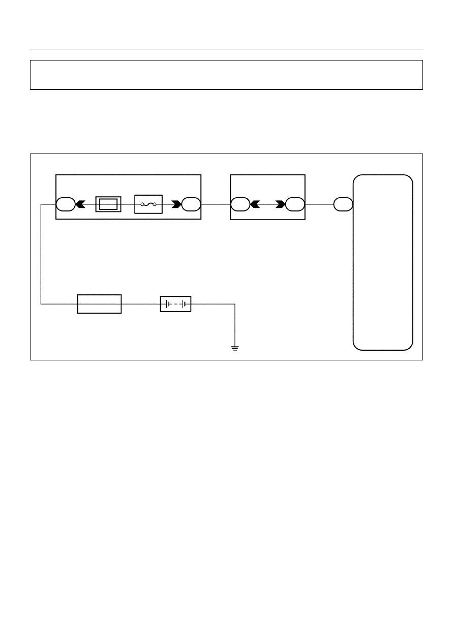
Back Up Power Source Circuit

CIRCUIT DESCRIPTION

This is the backup poser source for the A/C ECU (Combination meter ECU).  Power is supplied even when
the ignition switch is off and is used for diagnostic trouble code memory, etc.

WIRING DIAGRAM

DI3G6–03

I08349

+B

(–)

(+)

I08371

Engine Room J/B

ECU–B

DIAGNOSTICS

AIR CONDITIONING SYSTEM

DI–851

LEXUS RX300   (RM785E)

INSPECTION PROCEDURE

1

Check voltage between terminal +B of A/C ECU (Combination meter ECU) con-
nector and body ground.

PREPARATION:
Remove the A/C ECU (Combination meter ECU) with connec-
tor still connected.
CHECK:
Measure voltage between terminal +B of A/C ECU (Combina-
tion meter ECU) connector and body ground.
OK:

Voltage : Battery voltage

OK

Proceed to next circuit inspection shown on
problem symptoms table (See page DI–812).

NG

2

Check ECU–B fuse.

PREPARATION:
Remove ECU–B fuse from Engine Room J/B.
CHECK:
Check continuity of ECU–B fuse.
OK:

Continuity

NG

Check for short in all the harness and compo-
nents connected to the ECU–B fuse (See at-
tached wiring diagram).

OK

Check and repair harness and connector between A/C ECU (Combination meter ECU) and bat-
tery.

I08351

A/C ECU (Combina-
tion Meter ECU)

BLW

C12

4

IJ1

15*

1


4*

2

IG1

1

2

P–L

P–L

B3

1

W–B

3

J/C

B4

2

Blower Motor
Control Relay

B3

L–R

HEATER Relay

B4

1

R

B

2

1

B2 Blower Motor

IG1

W–B

IG1

2

B3

P–L

L–R

A

+B

SI

GND

M+

M–

IG*

1

IE*

2

J9*

1

 J5*

2

*

1

: LHD 

*

2

: RHD

3

DI–852

DIAGNOSTICS

AIR CONDITIONING SYSTEM

LEXUS RX300   (RM785E)

Blower Motor Circuit

CIRCUIT DESCRIPTION

This is the power source for the blower motor.

WIRING DIAGRAM

DI3G7–03

I08352

BLW(+)

(–)

I05290

1

2

LHD

RHD

DIAGNOSTICS

AIR CONDITIONING SYSTEM

DI–853

LEXUS RX300   (RM785E)

INSPECTION PROCEDURE

1

Check voltage between terminal BLW of A/C ECU (Combination meter ECU) con-
nector and body ground.

PREPARATION:
Remove the A/C ECU (Combination meter ECU) with connec-
tor still connected.
CHECK:
(a)

Turn ignition switch ON.

(b)

Operate blower motor.

(c)

Measure voltage between terminal BLW of A/C ECU
(Combination meter ECU) and body ground.

OK:

Voltage : 1 ± 3 V

OK

Proceed to next circuit inspection shown on
problem symptoms table (See page DI–812).

NG

2

Check blower motor.

PREPARATION:
Remove blower motor (See page AC–36).
CHECK:
Connect the positive (+) lead from the battery to terminal 2 of
blower motor connector and the negative (–) lead to terminal 1.
OK:

Blower motor operates smoothly.

NG

Replace blower motor.

OK


Content   ..  403  404  405  406   ..