Lexus RX300 (MCU15). Service manual - part 293
 

  Index      Lexus     Lexus RX300 series MCU15 - service and repair manual


Search            


Content   ..  291  292  293  294   ..


Lexus RX300 (MCU15). Service manual - part 293


H01015

H01036

H16250

H16301

Airbag 
Sensor 
Assembly

(–)

(+)

Side Airbag Sensor 
Assembly (RH)

SSR+

Airbag Sensor 
Assembly

ESR

SSR+

ESR

 →

DI–404

DIAGNOSTICS

SUPPLEMENTAL RESTRAINT SYSTEM

LEXUS RX300   (RM785E)

4

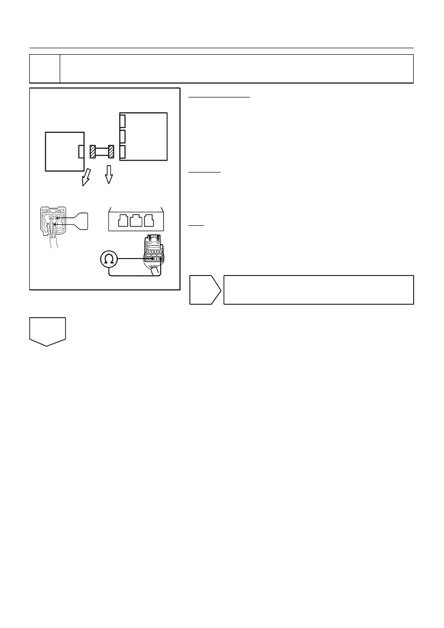
Check wire harness.

PREPARATION:
(a)

Disconnect the side airbag sensor assembly (RH) con-
nector.

(b)

Using a service wire, connect SSR+ and ESR of the con-
nector (on the side airbag sensor assembly side) between
the side airbag sensor assembly (RH) and airbag sensor
assembly.

CHECK:
For the connector (on the airbag sensor assembly side) be-
tween the side airbag sensor assembly (RH) and the airbag
sensor assembly, measure the resistance between SSR+ and
ESR.
OK:

Resistance: Below 1 

NG 

Repair or replace harness or connector be-
tween side airbag sensor assembly (RH) and
airbag sensor assembly.

OK

H01015

H01037

H16249

H16302

Airbag 
Sensor 
Assembly

(–)

(+)

Side Airbag Sensor 
Assembly (RH)

VUPR

Airbag Sensor 
Assembly

FSR

VUPR

FSR

DIAGNOSTICS

SUPPLEMENTAL RESTRAINT SYSTEM

DI–405

LEXUS RX300   (RM785E)

5

Check wire harness.

PREPARATION:
Using a service wire, connect VUPR and FSR of the connector
(on the side airbag sensor assembly side) between the side air-
bag sensor assembly (RH) and airbag sensor assembly.
CHECK:
For the connector (on the airbag sensor assembly side) be-
tween the side airbag sensor assembly (RH) and the airbag
sensor assembly, measure the resistance between VUPR and
FSR.
OK:

Resistance: Below 1 

NG

Repair or replace harness or connector be-
tween side airbag sensor assembly (RH) and
airbag sensor assembly.

OK

H01013
H01038

H01162

Side Airbag Sensor 
Assembly (RH)

Airbag 
Sensor 
Assembly

Airbag Sensor Assembly

SSR+

(+)

VUPR

FSR

(–)

AB0119
H01013
H01039

H08270

Side Airbag Sensor 
Assembly (RH)

Airbag 
Sensor 
Assembly

Airbag Sensor Assembly

SSR+

(+)

VUPR

FSR

(–)

ESR

ON

DI–406

DIAGNOSTICS

SUPPLEMENTAL RESTRAINT SYSTEM

LEXUS RX300   (RM785E)

6

Check wire harness (to ground).

CHECK:
For the connector (on the airbag sensor assembly side) be-
tween the side airbag sensor assembly (RH) and the airbag
sensor assembly, measure the resistance between body
ground and each of SSR+, VUPR and FSR.
OK:

Resistance: Below 1 

NG

Repair or replace harness or connector be-
tween side airbag sensor assembly (RH) and
airbag sensor assembly.

OK

7

Check wire harness (to B+).

CHECK:
(a)

Turn the ignition switch to ON.

(b)

For the connector (on the airbag sensor assembly side)
between the side airbag sensor assembly (RH) and the
airbag sensor assembly, measure the voltage between
the body ground and each of SSR+, VUPR, ESR and
FSR.

OK:

Voltage: 0 V

NG 

Repair or replace harness or connector be-
tween side airbag sensor assembly (RH) and
airbag sensor assembly.

OK

AB0119

H01012

H01065

H10600

H13119

Airbag 
Sensor 
Assembly

Side Airbag Sensor 
Assembly (RH)

CG

Tc

ON

 ←

DTC B1140/32

 ←

DLC3

DIAGNOSTICS

SUPPLEMENTAL RESTRAINT SYSTEM

DI–407

LEXUS RX300   (RM785E)

8

Is DTC B1140/32 out put again?

PREPARATION:
(a)

Connect the connector to the side airbag sensor assem-
bly (RH).

(b)

Connect the connector to the airbag sensor assembly.

(c)

Connect negative (–) terminal cable to the battery, and
wait at least for 2 seconds.

CHECK:
(a)

Turn the ignition switch to ON, and wait at least for 20 se-
conds.

(b)

Clear the DTC stored in memory (See step 5 on page 
DI–305).

(c)

Turn the ignition switch to LOCK, and wait at least for 20
seconds.

(d)

Turn the ignition switch to ON, and wait at least for 20 se-
conds.

(e)

Check the DTC (See page DI–305).

OK:

DTC B1140/32 is not output.

HINT:
Codes other than code B1140/32 may be output at this time, but
they are not relevant to this check.

NG

Go to step 9.

OK

From the results of the above inspection, the malfunctioning part can now be considered normal.
To make sure of this, use the simulation method to check.


Content   ..  291  292  293  294   ..