Lexus RX300 (MCU15). Service manual - part 251
 

  Index      Lexus     Lexus RX300 series MCU15 - service and repair manual


Search            


Content   ..  249  250  251  252   ..


Lexus RX300 (MCU15). Service manual - part 251


F08093

ABS Motor 
Relay

Brake Actuator

3

A21

2

2

2

ECU

28
MT

R/B No. 2

A7

A7

DI–236

DIAGNOSTICS

ABS & BA & TRC & VSC SYSTEM

LEXUS RX300   (RM785E)

4

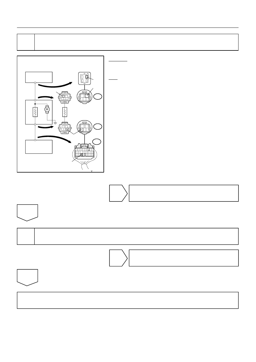
Check continuity between terminal 2 of ABS motor relay and terminal MT of skid
control ECU.

CHECK:
Check continuity between terminal 2 of R/B No. 2 (for ABS mo-
tor relay) and terminal MT of skid control ECU.
OK:

Continuity

HINT:
There is a resistance of 26 – 40 Ω between terminals A7 – 2 and
A7 – 3 of brake actuator.

NG

Repair or replace harness or brake actuator.

OK

5

Check for open and short circuit in harness and connector between ABS motor
relay and skid control ECU (See page IN–32).

NG

Repair or replace harness or connector.

OK

If the same code is still output after the DTC is deleted, check the contact condition of each con-
nection. If the connections are normal, the ECU may be defective.

DIAGNOSTICS

ABS & BA & TRC & VSC SYSTEM

DI–237

LEXUS RX300   (RM785E)

DTC

C0278 / 11, C0279 / 12

ABS Solenoid Relay Circuit

CIRCUIT DESCRIPTION

This relay supplies power to each ABS solenoid. After the ignition switch is turned ON, if the initial check is
OK, the relay goes on.

DTC No.

DTC Detecting Condition

Trouble Area

C0278 / 11

Conditions 1. and 2. continue for 0.2 sec. or more:

1. ECU terminal IG1 voltage is 9.5 V to 17.2 V and the

solenoid relay is ON, however the contact point of the

solenoid relay is OFF.

2. With solenoid relay ON driving, ECU terminal IG1 volt-

age becomes 9.5 V or less and the contact point of the

solenoid relay does not become ON.

S ABS solenoid relay

S ABS solenoid relay circuit

C0279 / 12

Immediately after ECU terminal IG1 becomes ON, and

solenoid relay is OFF, however the condition that 

the contact point of the solenoid relay is ON continues for

0.2 sec. or more.

DI84Q–01

F13425

Skid Control ECU

SFRH

SFLH

SFLR

SRRH

SRRR

SRLH

SRLR

1

2

6

ABS

AST

Battery

4

Brake Actuator

3

19

R+

SR

GR–R

2

A21

Y–G

GR

3

W–L

GR–L

R–B

10

A5

A5

G

G–B

BR–Y

L–Y

B–Y

2

2

SOL Relay

ABS

Motor Relay

A21

1

Fusible
Link Block
ABS

A7

4

A5

A5

A5

A5

A5

A5

A5

A5

A5

A6

A6

A7

A6

5

9

3

2

7

12

6

1

3

8

11

1

2

5

Y–B

B–O

V–W

BR–W

R

R–Y

8

9

7

1

16

8

21

7

15

22

3

2

4

5

6

A20

A21

A21

A21

A21

A20

A20

A21

A21

A20

A20

A20

A20

A21

A21

SFRR

SMV2

SMV1

SMC2

SMC1

SRC1

SRC2

B

R/B No. 2

2

L–Y

W

DI–238

DIAGNOSTICS

ABS & BA & TRC & VSC SYSTEM

LEXUS RX300   (RM785E)

WIRING DIAGRAM

F12364

R/B No. 2

(+)

(–)

1

DIAGNOSTICS

ABS & BA & TRC & VSC SYSTEM

DI–239

LEXUS RX300   (RM785E)

INSPECTION PROCEDURE

HINT:
Start the inspection from step 1 in case of using the hand–held tester and start from step 2 in case of not
using the hand–held tester.

1

Check ABS solenoid relay operation.

PREPARATION:
(a)

Connect the hand–held tester to the DLC3.

(b)

Turn the ignition switch ON, and push the hand–held tester main switch ON.

(c)

Select the ACTIVE TEST mode on the hand–held tester.

CHECK:
Check the operation sound of the ABS solenoid relay when operating it with the hand–held tester.
OK:

The operation sound of the ABS solenoid relay should be heard.

OK

Go to step 4.

NG

2

Check voltage between terminal 1 of R/B No. 2 (for ABS solendoid relay) and
body ground.

PREPARATION:
Remove the ABS solenoid relay from R/B No. 2.
CHECK:
Measure the voltage between terminal 1 of R/B No. 2 (for ABS
solenoid relay) and body ground.
OK:

Voltage: 10 – 14 V

NG

Check and repair harness or connector.

OK


Content   ..  249  250  251  252   ..