Lexus SC300 / Lexus SC400. Service manual - part 688
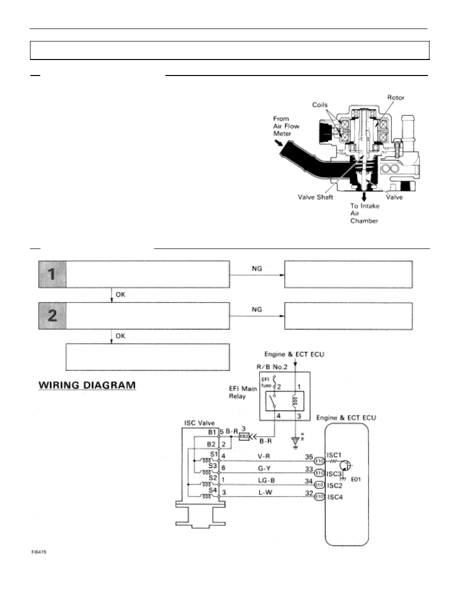
ISC Valve Circuit
CIRCUIT DESCRIPTION
The ISC valve is provided on the intake air chamber and in-
take air bypassing the throttle valve is directed to the ISC
valve through a hose.
A step motor is built into the ISC valve. It consists of four
coils, the magnetic rotor, valve shaft and valve. When cur-
rent flows to the coils due to signals from the ECU, the rotor
turns and moves the valve shaft forward or backward,
changing the clearance between the valve and the valve
seat.
In this way the intake air volume bypassing the throttle valve
is regulated, controlling the engine speed.
There are 125 possible positions to which the valve can be
opened.
DIAGNOSTIC CHART
DIAGNOSTIC CHART
Check operation for ISC valve.
Replace ISC valve.
Repair or replace harness or
connector.
Proceed to next circuit inspection shown on
matrix chart (See page
).
Check harness and connector between EFI
main relay, ISC valve and ECU.
TR–140
–
ENGINE TROUBLESHOOTING
Circuit Inspection