Lexus SC300 / Lexus SC400. Service manual - part 434
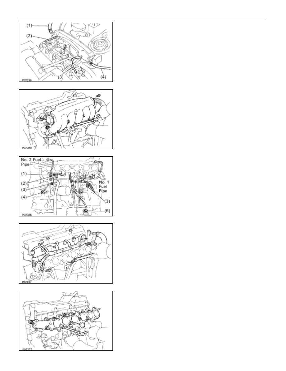
(b) Disconnect the following hoses:
(1) Vacuum hose from brake booster union
(2) Vacuum hose (from ACIS vacuum tank)
(3) Vacuum sensing hose
(4) Air hose (from PS air control valve)
(c) Remove the two bolts, and disconnect the data link
connector 1 and harness protector from the air intake
chamber.
(d) Remove the five bolts, two nuts and air intake chamber
and gasket.
13. REMOVE DELIVERY PIPE AND INJECTORS
(See steps 4, 5, 8 and 10 on pages FI–28 and 29)
14. REMOVE NO. 1 AND NO. 2 FUEL PIPES
15. DISCONNECT ENGINE WIRE FROM INTAKE MANIFOLD
(a) Disconnect the following connectors:
(1) Engine coolant temperature sensor connector
(2) Engine coolant temperature sender gauge connec-
tor
(3) Two knock sensor connectors
(4) Oil pressure switch connector
(5) Oil level sensor connector
(6) A/C compressor connector
(b) Remove the three nuts and two clamp bolts.
(c) Remove the two bolts, and disconnect the harness
protector from the intake manifold.
16. REMOVE
INTAKE
MANIFOLD
(a) Remove the two bolts and intake manifold stay.
(b) Remove the six bolts, two nuts, intake manifold and
gasket.
EM–38
–
ENGINE MECHANICAL
Cylinder Head