Lexus SC300 / Lexus SC400. Service manual - part 342
 

  Index      Lexus     Lexus SC300 / Lexus SC400 - service and repair manual


Search            


Content   ..  340  341  342  343   ..


Lexus SC300 / Lexus SC400. Service manual - part 342


3. 

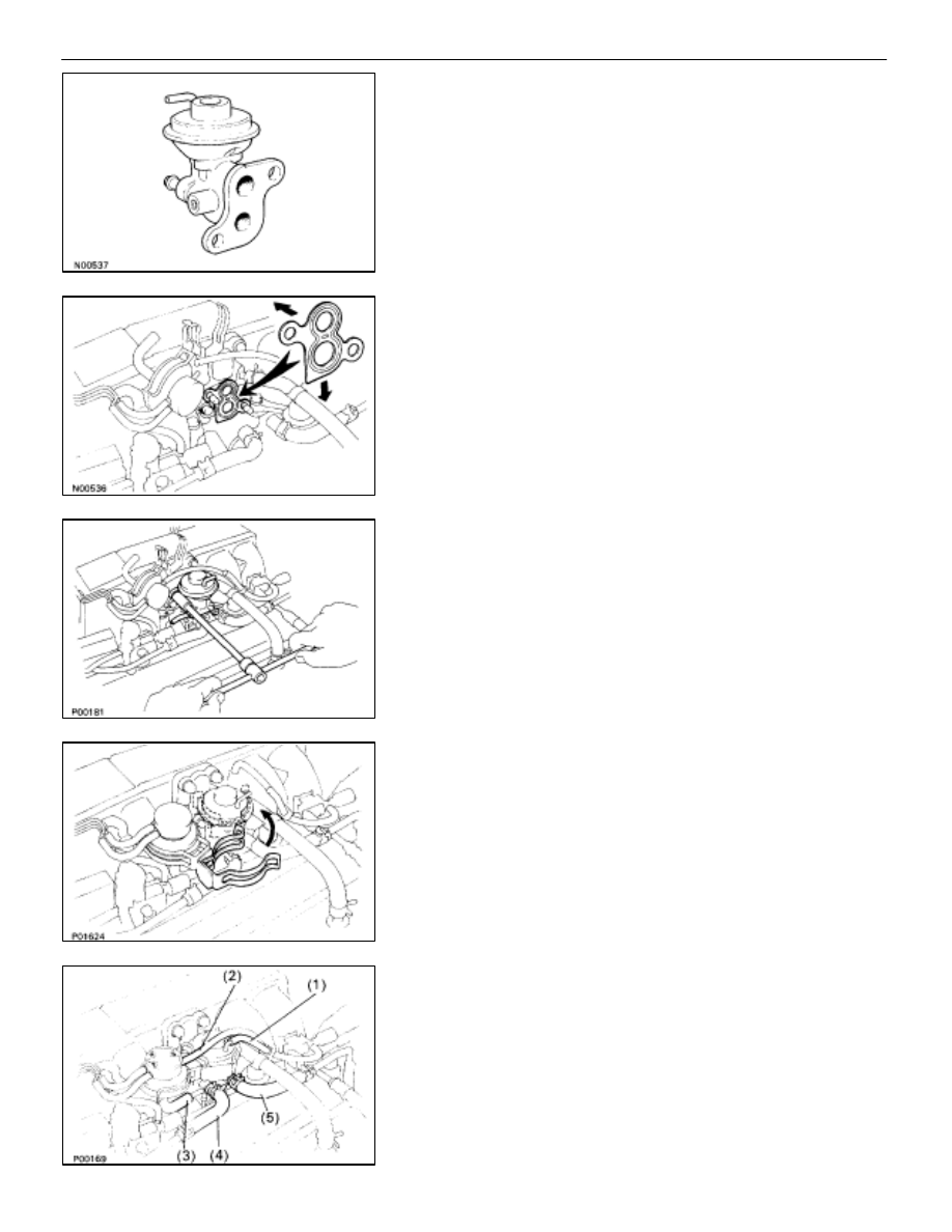
INSPECT EGR VALVE
Check for sticking and heavy carbon deposits.
If a problem is found, replace the EGR valve assembly.

4. 

REINSTALL EGR VALVE
(a)  Place a new gasket on the EGR valve adaptor.
NOTICE:

Do not touch the adaptor and EGR valve surfaces of the

gasket with your hand.

Align the port holes of the gasket and adaptor.

Be careful of the installation direction.

(b)  Install the EGR valve with the two nuts.

Torque: 18 N

m (185 kgf

cm, 13 ft

lbf)

(c)  Install the vacuum modulator bracket to the EGR valve.

(d)  Connect the following hoses:

(1)  Vacuum hose (from VSV) to EGR valve
(2)  Vacuum hose (from VSV) to EGR vacuum modula-

tor

(3)  Vacuum hose (from EGR vacuum modulator) to

EGR valve

(4)  Water by–pass hose (from ISC valve) to the EGR

valve

(5)  Water by–pass hose (from rear water by–pass

joint) to the EGR valve

5. 

REFILL WITH ENGINE COOLANT (See page 

CO–7

)

EMISSION CONTROL SYSTEMS

Exhaust Gas Recirculation (EGR) System

EC–25

THREE–WAY CATALYST (TWC) SYSTEM

DESCRIPTION

To reduce HC, CO and NOx emissions, they are oxidized, reduced and converted to nitrogen (N), carbon diox-

ide (CO) and water (HO) by the catalyst.

OPERATION

INSPECTION OF EXHAUST PIPE
ASSEMBLY

1.  CHECK CONNECTIONS FOR LOOSENSESS OR

DAMAGE

2. CHECK 

CLAMPS 

FOR 

WEAKNESS, 

CRACKS OR

DAMAGE

INSPECTION OF CATALYTIC
CONVERTER

CHECK FOR DENTS OR DAMAGE

If any part of the protector is damaged or dented to the extent
that is contacts the catalyst, repair or replace it.

INSPECTION OF HEAT INSULATOR

1. 

CHECK HEAT INSULATOR FOR DAMAGE

2. CHECK 

FOR 

ADEQUATE 

CLEARANCE 

BETWEEN

CATALYTIC CONVERTER AND HEAR INSULATOR

EMISSION CONTROL SYSTEMS

Three–way Catalyst (TWC) System

EC–17

COMPONENTS

REPLACEMENT OF CATALYTIC
CONVERTERS

(Front Catalytic Converter)

1. 

REMOVE CATALYTIC CONVERTER (FRONT)
(a)  Check that the converter is cool.
(b)  Remove the two bolts and nuts holding the catalytic

converters to the front exhaust pipe.

(c)  Disconnect the front exhaust pipe from the catalytic

converter, and remove the gasket.

(d)  Remove the four nuts holding the catalytic converter to

the exhaust manifold.

2. REINSTALL 

CATALYTIC 

CONVERTER

(a)  Install a new gasket and the catalytic converter to the

exhaust manifold with four new nuts.

Torque: 62 N

m (630 kgf

cm, 46 ft

lbf)

(b)  Install a new gasket to front end of the front exhaust

pipe, and torque the front exhaust pipe to the catalytic
converter.

Torque: 43 N

m (440 kgf

cm, 32 ft

lbf)

EC–18

EMISSION CONTROL SYSTEMS

Three–way Catalyst (TWC) System

(Rear Catalytic Converter)
1. (USA 

Spec.)

REMOVE SUB–OXYGEN SENSOR
Remove the two nuts and sub–oxygen sensor from the front
exhaust pipe.

2. 

REMOVE REAR CATALYTIC CONVERTER (FRONT
EXHAUST PIPE)
(a)  Remove the two bolts and nuts holding the front exhaust

pipe to the center exhaust pipe.

(b)  Remove the two bolts and nuts holding the front exhaust

pipe to the front catalytic converter, and remove the front
exhaust pipe and two gaskets.

3.  REINSTALL REAR CATALYTIC CONVERTER (FRONT

EXHAUST PIPE)
Install the two new gaskets, the front exhaust pipe with the
four bolts and new nuts.

Torque: 43 N

m (440 kgf

cm, 32 ft

lbf)

4. (USA 

Spec.)

REINSTALL SUB–OXYGEN SENSOR
Install the new gasket, the sub–oxygen sensor to the front ex-
haust pipe with the two nuts.

Torque: 18 N

m (180 kgf

cm, 13 ft

lbf)

EMISSION CONTROL SYSTEMS

Three–way Catalyst (TWC) System

EC–19


Content   ..  340  341  342  343   ..