Lexus SC300 / Lexus SC400. Service manual - part 31
ÑÑÑÑÑÑÑÑÑÑÑÑÑÑÑÑÑÑÑÑÑÑÑÑÑÑÑÑÑÑÑÑÑÑÑÑ
ÑÑÑÑÑÑÑÑÑÑÑÑÑÑÑÑÑÑÑÑÑÑÑÑÑÑÑÑÑÑÑÑÑÑÑÑ
ÑÑÑÑÑÑÑÑÑÑÑÑÑÑÑÑÑÑÑÑÑÑÑÑÑÑÑÑÑÑÑÑÑÑÑÑ
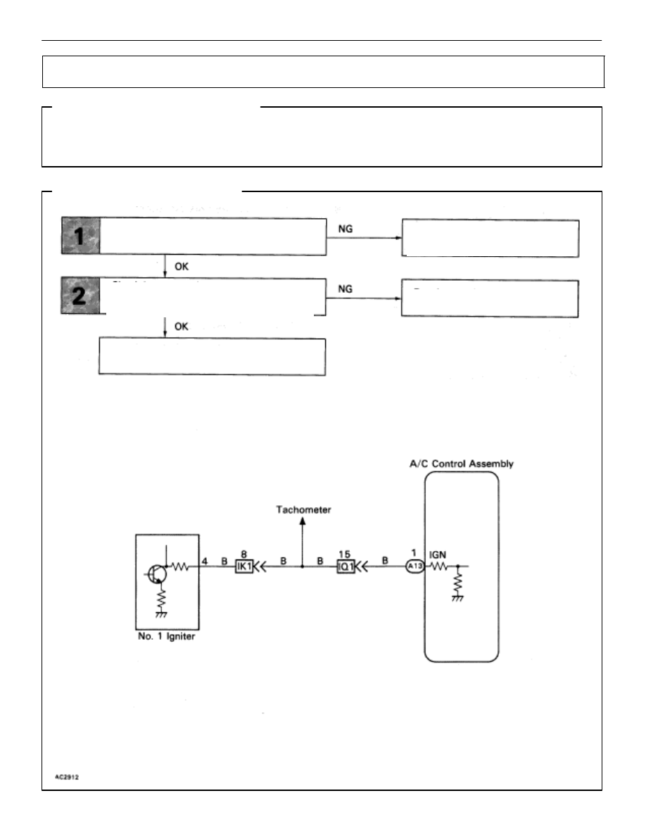
Igniter Circuit
CIRCUIT DESCRIPTION
The air conditioner control assembly monitors the engine speed through signals sent from the igniter.
The air conditioner control assembly uses these signals and compressor speed signals to detect the
compressor lock condition.
DIAGNOSTIC CHART
WIRING DIAGRAM
Check operation of tachometer.
Check harness and connector between air
conditioner control assembly and igniter
(See page
Proceed to combination meter
troubleshooting (See page
Proceed to next circuit inspection
shown on matrix chart (See page
).
Repair or replace harness or
connector.
AC–82
–
AIR CONDITIONING SYSTEM
Troubleshooting