Lexus ES300 (1997 year). Service manual - part 388
 

  Index      Lexus     Lexus ES300 - service and repair manual 1997 year


Search            


Content   ..  386  387  388  389   ..


Lexus ES300 (1997 year). Service manual - part 388


DI0AY–01

W02759

1

2

3

4

5

6

7

8

9

10

A

B

DIAGNOSTICS

SUPPLEMENTAL RESTRAINT SYSTEM

DI–329

481

1997 LEXUS ES300   (RM511U)

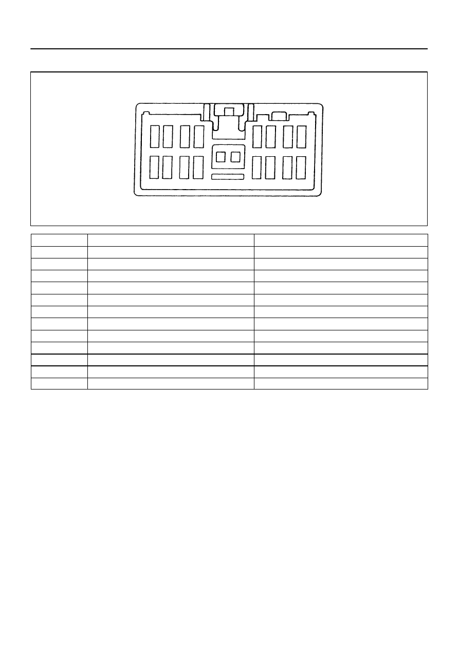
TERMINALS OF ECM

No.

Symbol

Terminal Name

A

Electrical Connection Check Mechanism

B

Electrical Connection Check Mechanism

1

P–

Squib 

 (

Passenger)

2

P+

Squib  (Passenger)

3

LA

SRS Warning Light

4

D–

Squib  (Driver)

5

D+

Squib  (Driver)

6

Tc

Diagnosis

7

E2

Ground

8

E1

Ground

9

IG2

Power Source (IGN Fuse)

10

ACC

Power Source (CIG Fuse)

DI0AZ–01

DI–330

DIAGNOSTICS

SUPPLEMENTAL RESTRAINT SYSTEM

482

1997 LEXUS ES300   (RM511U)

PROBLEM SYMPTOMS TABLE

Proceed with troubleshooting of each circuit in the table below.

Symptom

Suspect Area

See page


With the ignition switch at ACC or ON, the SRS warning light

sometimes lights up after approx. 6 seconds have elapsed.


SRS warning light is always lit up even when ignition switch is in

the LOCK position.


SRS warning light circuit

(Always lights up when ignition switch is in LOCK posi-

tion.)

DI–362


With the ignition switch at ACC or ON, the SRS warning lights

does not light up.


SRS warning light circuit 

(Does not light up when ignition switch is turned to ACC or

ON.)

DI–364


DTC not displayed.


SRS warning light is always lit up a DTC check procedure.


DTC displayed without Tc and E1 terminal connection.


Tc  terminal circuit

DI–367

DI0B0–01

R16017

Airbag Sensor Assembly

P Squib

D Squib

Spiral
Cable

1

2

2

1

2

P+

P–

D+

D–

Y–R

Y–B

Y–G

Y

3

6

7

DIAGNOSTICS

SUPPLEMENTAL RESTRAINT SYSTEM

DI–331

483

1997 LEXUS ES300   (RM511U)

CIRCUIT INSPECTION

DTC

   11

Short in Squib Circuit (to Ground)

CIRCUIT DESCRIPTION

The squib circuit consists of the airbag sensor assembly, spiral cable, steering wheel pad and front passen-
ger airbag assembly. If causes the SRS to deploy when the SRS deployment conditions are satisfied.
For details of the function of each component, see OPERATION on page 

RS–2

DTC 11 is recorded when ground short is detected in the squib circuit.

DTC No.

DTC Detecting Condition

Trouble Area

11


Short circuit in squib wire harness (to ground)


Squib malfunction


Spiral cable malfunction


Airbag sensor assembly malfunction


Steering wheel pad (D squib)


Front passenger airbag assembly (P squib)


Spiral cable


Airbag sensor assembly


Wire harness

WIRING DIAGRAM

R05901

R14301

H00053

Airbag Sensor
Assembly

P Squib

D Squib

Spiral
Cable

D+

(+)

(–)

R05896

R14301

H00054

Spiral
Cable

Airbag Sensor
Assembly

P Squib

D Squib

P+

(+)

(–)

DI–332

DIAGNOSTICS

SUPPLEMENTAL RESTRAINT SYSTEM

484

1997 LEXUS ES300   (RM511U)

INSPECTION PROCEDURE

1

Preparation. (See step ” 1 ” on page 

DI–359

)

2

Check D squib circuit.

CHECK:
For the connector (on the spiral cable side) between the spiral
cable and steering wheel pad, measure the resistance between
D+ and body ground.
OK:

Resistance: 1M

 or Higher

NG

Go to step ” 7 ”.

OK

3

Check P squib circuit.

CHECK:
For the connector (on the airbag sensor assembly side) be-
tween the airbag sensor assembly and front passenger airbag
assembly, measure the resistance between P+ and body
ground.
OK:

Resistance: 1M

 or Higher


Content   ..  386  387  388  389   ..