Lexus ES300 (1997 year). Service manual - part 288
 

  Index      Lexus     Lexus ES300 - service and repair manual 1997 year


Search            


Content   ..  286  287  288  289   ..


Lexus ES300 (1997 year). Service manual - part 288


BR071–04

BR5332

BR0897

BR0828

R00343

Shim

Clearance

R00313

BRAKE

PARKING BRAKE

BR–43

1158

1997 LEXUS ES300   (RM511U)

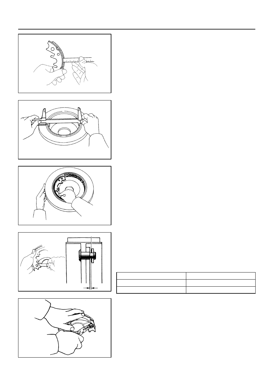
INSPECTION

1.

INSPECT DISASSEMBLED PARTS

Inspect the disassembled parts for wear, rust or damage.
2.

MEASURE BRAKE SHOE LINING THICKNESS

Using a ruler, measure the thickness of the shoe lining.

Standard thickness: 2.0 mm (0.079 in.)
Minimum thickness: 1.0 mm (0.039 in.)

If the lining thickness is at the minimum thickness or less, or if
there is severe, uneven wear, replace the brake shoe.

3.

MEASURE DISC INSIDE DIAMETER

Using a vernier calipers, measure the inside diameter of the
disc.

Standard inside diameter: 170 mm (6.69 in.)
Maximum inside diameter: 171 mm (6.73 in.)

Replace the disc if the inside diameter is at the maximum value
or more. Replace the disc or grind it with a lathe if the disc is
scored or is worn unevenly.

4.

INSPECT PARKING BRAKE LINING AND DISC FOR
PROPER CONTACT

Apply chalk to the inside surface of the disc, then grind down
the brake shoe lining to fit. If the contact between the disc and
the brake shoe lining is improper, repair it using a brake shoe
grinder or replace the brake shoe assembly.

5.

MEASURE CLEARANCE BETWEEN PARKING
BRAKE SHOE AND LEVER

Using a feeler gauge, measure the clearance.

Standard clearance: Less than 0.35 mm (0.0138 in.)

If the clearance is not within the specification, replace the shim
with one of the correct size.

Shim Thickness

Shim Thickness

0.3 mm (0.012 in.)

0.9 mm (0.035 in.)

0.6 mm (0.024 in.)

6.

IF NECESSARY, REPLACE SHIM

(a)

Using a screwdriver, remove the C–washer and shim.

(b)

Remove the parking brake lever, and install the correct
size shim.

(c)

Install the parking brake lever with a new C–washer.

(d)

Remeasure the clearance.

BR072–01

BR0823

Contract

Expand

BR–44

BRAKE

PARKING BRAKE

1159

1997 LEXUS ES300   (RM511U)

REASSEMBLY

Reassembly is in the reverse order of disassembly (See
page 

BR–42

).

NOTICE:
Apply high temperature grease to the parts indicated by the
arrows (See page 

BR–41

).

1.

ADJUST PARKING BRAKE SHOE CLEARANCE

(a)

Temporarily install the hub nuts.

(b)

Remove the hole plug.

(c)

Turn the adjuster and expand the shoes until the disc
locks.

(d)

Return the adjuster 8 notches.

(e)

Install the hole plug.

2.

SETTLING PARKING BRAKE SHOES AND DISC

(a)

Depress the parking brake pedal with 147 N (15 kgf, 33
lbf)

(b)

Drive the vehicle at about 50 km/h (31 mph) on a safe, lev-
el and dry road for about 400 meters (0.25 mile) in this
condition.

(c)

Repeat this procedure 2 or 3 times.

3.

RECHECK AND ADJUST PARKING BRAKE PEDAL
TRAVEL (See page 

BR–8

)

BR073–04

W04698

SST

SST

BRAKE

PROPORTIONING VALVE (P VALVE)

BR–45

1160

1997 LEXUS ES300   (RM511U)

PROPORTIONING VALVE (P VALVE)

ON–VEHICLE INSPECTION

1.

INSTALL LSPV GAUGE (SST) AND BLEED AIR
SST

09709–29018

2.

BLEED AIR FROM FLUID PRESSURE GAUGE

3.

RAISE MASTER CYLINDER PRESSURE AND CHECK REAR CALIPER PRESSURE

Master cylinder fluid pressure

Rear brake caliper fluid pressure

2,942 kPa (30 kgf/cm

2

, 427 psi)

2,942 kPa (30 kgf/cm

2

, 427 psi)

7,845 kPa (80 kgf/cm

2

, 1,138 psi)

5,884 kPa (60 kgf/cm

2

, 853 psi)

If the rear brake caliper pressure is incorrect, replace the P valve assembly.
4.

BLEED BRAKE SYSTEM (See page 

BR–4

)

5.

CHECK FOR LEAKS

R09422

(SST)

ABS
Actuator

Sub – Wire Harness G (SST)

Sub – Wire Harness L (SST)

Sub – Wire Harness I (SST)

BR07B–01

W03244

BR–46

BRAKE

ABS ACTUATOR

1161

1997 LEXUS ES300   (RM511U)

ABS ACTUATOR

ON–VEHICLE INSPECTION

HINT:
Using the ABS actuator checker (SST), check the operation of
the actuator. If the actuator does not operate, check the opera-
tion of sub–wire harness G according to the instructions on
pages 

DI–240

 and 

DI–243

. If the solenoid and/or pump motor

relay are abnormal, replace the relay and inspect the actuator
operation again.
1.

INSPECT BATTERY POSITIVE VOLTAGE
Battery positive voltage: 10 – 14 V

2.

DISCONNECT CONNECTORS

Disconnect the 2 connectors from the actuator.
3.

CONNECT ACTUATOR CHECKER (SST)

(a)

Connect the actuator checker (SST) to the actuator side
wire harness via the sub–wire harness (SST), as shown.
SST

09990–00150,  09990–00250, 09990–00300,
09990–00360

(b)

Connect the red cable of the checker to the battery posi-
tive (+) terminal and black cable to the negative (–) termi-
nal. Connect the black cable of the sub–wire harness to
the battery negative (–) terminal or body ground.


Content   ..  286  287  288  289   ..