Lexus ES300 (1997 year). Service manual - part 27
 

  Index      Lexus     Lexus ES300 - service and repair manual 1997 year


Search            


Content   ..  25  26  27  28   ..


Lexus ES300 (1997 year). Service manual - part 27


106

BODY ELECTRICAL — ACCESSORIES

4. Function

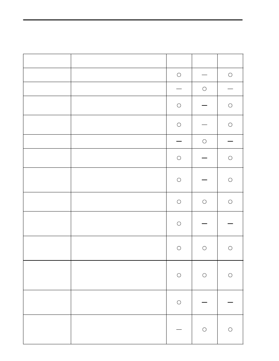
The following table is a comparison of the functions of wireless door lock remote control system between
the new ES300, previous ES300 and ’97 LS400.

Function

Outline

New

ES300

Previous

ES300

’97

LS400

All Doors Lock
Operation

Pressing the “door lock” switch of the
transmitter locks all doors.

All Doors Lock
Operation

Pressing the transmitter switch locks all doors.

Driver’s Door
Unlock
Operation

Pressing the “door unlock” switch of the
transmitter once unlocks only the driver’s
door.

All Doors Unlock
Operation

Pressing the “door unlock” switch twice
within 3 seconds opens all doors after opening
the driver’s door.

All Doors Unlock
Operation

Pressing the transmitter switch unlocks all
doors.

Trunk Lid Open
Operation

Keeping the “trunk lid opener” switch of the
transmitter pressed longer than 0.8 seconds
opens the trunk lid.

Panic Alarm
Operation

Pressing the “panic” switch of the transmitter
activates the alarm of the theft deterrent
system (to sound the horn and flash the
headlights and taillights).

Operation
Verification
Beeper Function

When the transmitter is used to lock or unlock
the doors, this function sounds the beeper to
inform that the operation has been completed.

Operation
Verification
Light Function

When the transmitter is used to lock or unlock
the doors, this function flashes the parking
lights and taillights to inform that the
operation has been completed.

Auto Lock Function

If none of the doors are opened within 30
seconds after they are unlocked by the
wireless door lock remote control, all the
doors are locked again automatically.

Transmitter Switch
Misoperation
Prevention Function

When an ignition key is in the ignition key
cylinder or any of the doors is not closed
completely, the wireless door lock remote
control is temporarily canceled to prevent
misoperation.

Repeat Function

If a door is not locked in response to the
locking operation of the transmitter, the
wireless door lock ECU will output a lock
signal once after 2 seconds.

Repeat Function

If a door is not locked or unlocked in response
to the locking or unlocking operation of the
transmitter, the wireless door lock ECU will
output a lock or unlock signal 10 times at 2-
second intervals.

107

BODY ELECTRICAL — ACCESSORIES

Function

Outline

New

ES300

Previous

ES300

’97

LS400

Door Ajar Warning
Function

If any door is open or ajar, pressing the “door
lock” switch of the transmitter will cause the
beeper to sound.

Beeper Volume
Control Function

The beeper volume can be adjusted by
adjusting the wireless door lock beeper
controller.

Security Function

If the wireless door lock ECU receives more
than 10 types of incorrect codes within 10
minutes, it will stop receiving all codes,
including the correct code.

Send an operation signal as a cryptographic
code.

Transmitter
Recognition Code
Registration Function

4 types of transmitter recognition codes can
be registered (written to and stored) in the
EEPROM that is contained in the wireless
door lock ECU.

Operation Verification Light Function

When the doors are locked by the transmitter
switch operation, the parking light and
taillight flashes once to confirm that the
operation has been completed.
Similarly, the parking light flashes twice
when the doors are unlocked.

 Light Flash Patterns 

Transmitter Recognition Code Registration Function

In addition to the 3 special coded ID registration function modes (rewrite mode, add mode and confirm
mode), a prohibit mode has been newly provided in the registration function of the transmitter
recognition code.
The table below shows the 4 special coded ID registration function modes through which up to 4 different
codes can be registered. The codes are electronically registered (written to and stored) in the EEPROM.
For details of the recognition code registration procedure, refer to the 1997 ES300 Repair Manual (Pub.
No. RM511 U) to register the codes correctly.

Mode

Function

Rewrite Mode

Erases all previously registered codes and registers only the newly received
codes. This mode is used whenever a transmitter or the wireless door lock
ECU is replaced.

Add Mode

Adds a newly received code while preserving any previously registered codes.
This mode is used when adding a new transmitter. If the number of codes
exceeds 4, the oldest registered code is erased first.

Confirm Mode

Confirms how many codes are currently registered. When adding a new code,
this mode is used to check how many codes already exist.

Prohibit Mode

To delete all the registered codes and to prohibit the wireless door lock
function. This mode is used when the transmitter is lost.

108

BODY ELECTRICAL — ACCESSORIES


 SRS AIRBAG

1. General


The SRS (Supplemental Restraint System) airbag is designed to help lessening the shock to the driver and
front passenger as a supplement to the seat belt.
In a collision, the airbag sensor detects the shock and if the front-to-rear shock is greater than a specified
value, the airbags stored in the steering wheel pad for the driver and above the glove box for the front
passenger inflate instantly to help reducing the likelihood of the driver’s or front passenger’s head and
chest directly hitting the steering wheel or instrument panel.


As in the ’95 LS400, a 1 -sensor type airbag system is used, in which the detection of deceleration during
a collision is accomplished by the airbag sensor enclosed in the airbag sensor assembly.


The airbag system is controlled by the airbag sensor assembly. It has a self-diagnosis function. When it
detects a system malfunction, it lights up the SRS Warning light on the combination meter to alert the
driver.

The basic construction and operation are the same as in the ’95 LS400. However, the construction and
operation of inflator for front passenger has been changed.

 System Diagram 

The activation processes of the SRS airbag is as illustrated below.

109

BODY ELECTRICAL — ACCESSORIES

2. Layout of Components

The major function parts of the airbag system are shown below.

3. Wiring Diagram


Content   ..  25  26  27  28   ..