Lexus GS300/400 (2000 year). Service manual - part 108
 

  Index      Lexus     Lexus GS300/400 - service and repair manual 2000 year


Search            


Content   ..  106  107  108  109   ..


Lexus GS300/400 (2000 year). Service manual - part 108


F02823

F02824

F02825

BRAKE

BRAKE FLUID

BR–7

2115

(i)

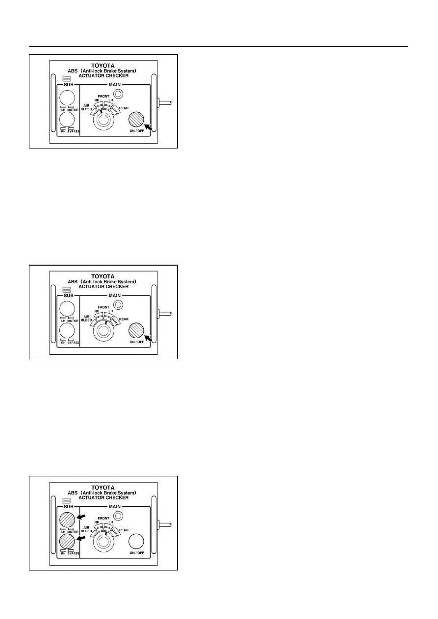
Bleed right front brake line.
(1)

Turn the selector switch of the actuator checker to
the ”FRONT RH” position.

(2)

Push and hold in MAIN push switch, depress the
brake pedal and hold it to bleed the right front brake
caliper.

NOTICE:
Do not keep the MAIN switch pushed in for more than 10 se-
conds. When operating it continuously, set the interval of
more than 20 seconds.

(3)

Repeat step (2) until there are no more air bubbles
in the fluid.

(j)

Bleed left front brake line.
(1)

Turn the selector switch of the actuator checker to
the ”FRONT LH” position.

(2)

Push and hold in the MAIN push switch, depress the
brake pedal and hold it to bleed the left front brake
caliper.

NOTICE:
Do not keep the MAIN switch pushed in for more than 10 se-
conds. When operating it continuously, set the interval of
more than 20 seconds.

(3)

Repeat step (2) until there are no more air bubbles
in the fluid.

(k)

Bleed right rear brake line.
(1)

Push and hold in the ”SUB LH” and ”SUB RH”
switches, bleed the right rear brake caliper.

NOTICE:
Do not keep the MAIN switch pushed in for more than 10 se-
conds. When operating it continuously, set the interval of
more than 20 seconds.

(2)

Repeat step (1) until there are no more air bubbles
in the fluid.

F02851

BR–8

BRAKE

BRAKE FLUID

2116

(l)

Observe the procedure in step (k) and bleed left rear
brake line.

(m)

Disconnect the actuator checker (SST) and sub–wire har-
ness (SST) from the actuator.
SST

09990–00150, 09990–00480

(n)

Connect the 2 connectors to the hydraulic brake booster.

(o)

Clear the DTC (See page 

DI–389

).

4.

BLEED BRAKE LINE

(a)

Connect the vinyl tube to the brake caliper.

(b)

Depress the brake pedal several times, then loosen the
bleeder plug with the pedal held down.

(c)

At the point when fluid stops coming out, tighten the
bleeder plug, then release the brake pedal.

(d)

Repeat (b) and (c) until all the air in the fluid has been bled
out.

(e)

Repeat the above procedure to bleed the brake line for
each wheel.
Torque: 11 N·m (110 kgf·cm, 8 ft·lbf)

5.

CHECK FLUID LEVEL IN RESERVOIR

(a)

With the ignition switch OFF, depress the brake pedal
more than 40 times.

HINT:
When a pressure in power supply system is released, reaction
force becomes heavy and stroke becomes shorter.
(b)

Remove the reservoir cap. Add brake fluid up to the
”MAX” line.
Fluid: SAE J1703 or FMVSS NO. 116 DOT3

BR0K8–09

F06044

Non–reusable part


Gasket

Hydraulic Brake Booster
Assembly

13 (130, 9)

End Pad

Brake Fluid Level Warning
Connector

Return Spring

No. 7 Heater to Register Duct

No. 1 Under Cover

No. 1 Safety Pad

15 (155, 11)

15 (155, 11)

15 (155, 11)

15 (155, 11)

N·m (kgf·cm, ft·lbf)

: Specified torque

Pin

Clip

BR–48

BRAKE

HYDRAULIC BRAKE BOOSTER

2156

COMPONENTS

F06045

Reservoir Set Screw

Hydraulic Brake Booster

Oil Pressure
Sensor

No. 1 Accumulator
Bracket

No. 2
Accumulator
Bracket

No. 1 Pump
Bracket

Actuator No. 1 Tube

Accumulator


O–ring

Spring

Silencer Tube

Grommet

No. 2 Piston

No. 1 Piston

Snap Ring

Boot

Clevis

Reservoir

Cap

No. 2 Pump
Bracket

Sleeve

Collar

Booster Pump Motor

Cushion

Washer

Actuator Hose

15 (155, 11)

54 (550, 36)

1.7 (17.5, 15.2 in.·lbf)

81 (830, 60)

Non–reusable part


Cushion

Cushion

Collar

Cushion

25 (260, 19)

N·m (kgf·cm, ft·lbf)

: Specified torque

Spacer


O–ring

Clamp


Wire Harness

BRAKE

HYDRAULIC BRAKE BOOSTER

BR–49

2157


Content   ..  106  107  108  109   ..