Lexus GS300/400 (2000 year). Service manual - part 85
I04035
From Back Side
11
I01200
2
1
3
5
2
5
1
3
BE–54
–
BODY ELECTRICAL
FOG LIGHT SYSTEM
2355
3.
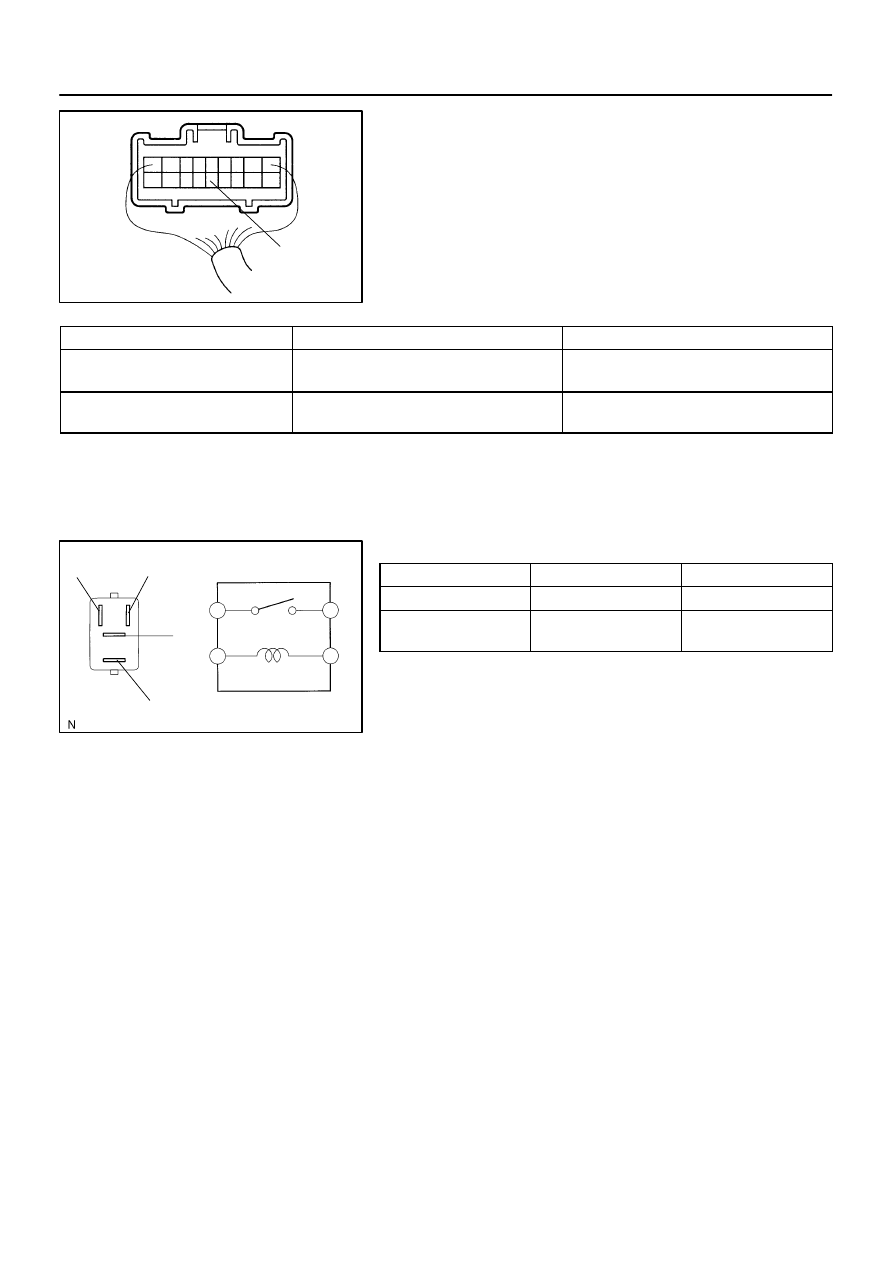
INSPECT FOG LIGHT SWITCH CIRCUIT
Connector connected:
Connect the wire harness side connector to the light control and
dimmer switch and inspect the connector from the back side, as
shown.
Tester connection
Condition
Specified condition
11 – Ground
Light control switch HEAD and headlight dimmer
switch LO and fog light switch ON
No voltage
11 – Ground
Light control switch HEAD and headlight dimmer
switch HI or FLASH and fog light switch ON
Battery positive voltage
If circuit is not as specified, inspect the wire harness.
4.
INSPECT FOG LIGHT RELAY CONTINUITY
Condition
Tester connection
Specified condition
Constant
1 – 2
Continuity
Apply B+ between
terminals 1 and 2.
3 – 5
Continuity
If continuity is not as specified, replace the relay.
5.
INSPECT FOG LIGHT RELAY CIRCUIT
(See page