Jeep Compass (2019 year). Manual - part 18
 

  Index      Jeep     Jeep Compass - service manual 2019 year in english


Search            copyright infringement  


Content   ..  16  17  18  19   ..


Jeep Compass (2019 year). Manual - part 18


NOTE:

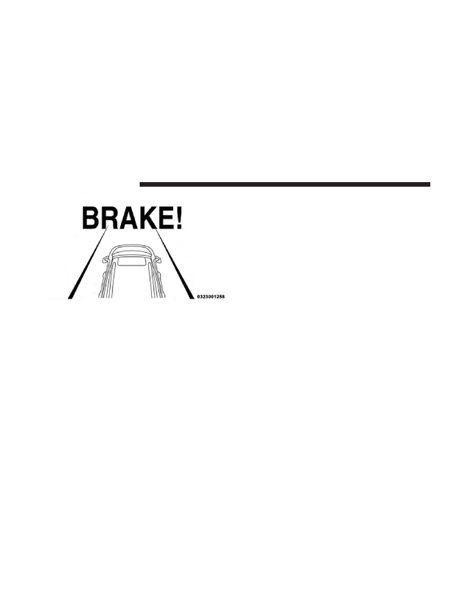
The “Brake!” Screen in the instrument cluster

display is a warning for the driver to take action and does
not necessarily mean that the Forward Collision Warning
system is applying the brakes autonomously.

Overtake Aid

When driving with ACC engaged and following a vehicle,
the system will provide an additional acceleration up to the
ACC set speed to assist in passing the vehicle. This
additional acceleration is triggered when the driver utilizes
the left turn signal and will only be active when passing on
the left hand side.

ACC Operation At Stop

In the event that the ACC system brings your vehicle to a
standstill while following a target vehicle, if the target
vehicle starts moving within two seconds of your vehicle
coming to a standstill, your vehicle will resume motion
without the need for any driver action.

If the target vehicle does not start moving within two
seconds of your vehicle coming to a standstill, the driver
will either have to push the RES (resume) button, or apply
the accelerator pedal to reengage the ACC to the existing
Set Speed.

NOTE:

After the ACC system holds your vehicle at a

standstill for approximately three consecutive minutes, the
parking brake will be activated, and the ACC system will
be cancelled.

While ACC is holding your vehicle at a standstill, if the
driver seatbelt is unbuckled or the driver door is opened,
the parking brake will be activated, and the ACC system
will be cancelled.

Brake Alert

276

STARTING AND OPERATING

WARNING!

When the ACC system is resumed, the driver must
ensure that there are no pedestrians, vehicles or objects
in the path of the vehicle. Failure to follow these
warnings can result in a collision and death or serious
personal injury.

Adaptive Cruise Control (ACC) Menu

The instrument cluster display shows the current ACC
system settings. The instrument cluster display is located
in the center of the instrument cluster. The information it
displays depends on ACC system status.

Push the Adaptive Cruise Control (ACC) on/off button
(located on the steering wheel) until one of the following
shows in the instrument cluster display:

Adaptive Cruise Control Off

When ACC is deactivated, the display will read “Adaptive
Cruise Control Off.”

Adaptive Cruise Control Ready

When ACC is activated but the vehicle speed setting has
not been selected, the display will read “Adaptive Cruise
Control Ready.”

Push the SET (+) or the SET (-) button (located on the
steering wheel) and the following will read in the instru-
ment cluster display:

ACC SET

When ACC is set, the set speed will appear in the instru-
ment cluster display.

The ACC screen may display once again if any ACC
activity occurs, which may include any of the following:
• System Cancel
• Driver Override
• System Off
• ACC Proximity Warning
• ACC Unavailable Warning

• The instrument cluster display will return to the last

display selected after five seconds of no ACC display
activity

6

STARTING AND OPERATING

277

Display Warnings And Maintenance

“Wipe Front Radar Sensor In Front Of Vehicle”
Warning

The “ACC/FCW Unavailable Wipe Front Radar Sensor”
warning will display and also a chime will indicate when
conditions temporarily limit system performance.

This most often occurs at times of poor visibility, such as in
snow or heavy rain. The ACC system may also become
temporarily blinded due to obstructions, such as mud, dirt
or ice. In these cases, the instrument cluster display will
read “ACC/FCW Unavailable Wipe Front Radar Sensor”
and the system will deactivate.

The “ACC/FCW Unavailable Wipe Front Radar Sensor”
message can sometimes be displayed while driving in
highly reflective areas (i.e. tunnels with reflective tiles, or
ice and snow). The ACC system will recover after the
vehicle has left these areas. Under rare conditions, when
the radar is not tracking any vehicles or objects in its path
this warning may temporarily occur.

NOTE:

If the “ACC/FCW Unavailable Wipe Front Radar

Sensor” warning is active Normal (Fixed Speed) Cruise
Control is still available. For additional information refer to
“Normal (Fixed Speed) Cruise Control Mode” in this
section.

If weather conditions are not a factor, the driver should
examine the sensor. It may require cleaning or removal of
an obstruction. The sensor is located in the center of the
vehicle behind the lower grille.

To keep the ACC System operating properly, it is important
to note the following maintenance items:
• Always keep the sensor clean. Carefully wipe the sensor

lens with a soft cloth. Be cautious not to damage the
sensor lens.

• Do not remove any screws from the sensor. Doing so

could cause an ACC system malfunction or failure and
require a sensor realignment.

• If the sensor or front end of the vehicle is damaged due

to a collision, see your authorized dealer for service.

• Do not attach or install any accessories near the sensor,

including transparent material or aftermarket grilles.
Doing so could cause an ACC system failure or malfunc-
tion.

278

STARTING AND OPERATING

When the condition that deactivated the system is no
longer present, the system will return to the “Adaptive
Cruise Control Off” state and will resume function by
simply reactivating it.

NOTE:
• If the “ACC/FCW Unavailable Wipe Front Radar Sen-

sor” message occurs frequently (e.g. more than once on
every trip) without any snow, rain, mud, or other
obstruction, have the radar sensor realigned at your
authorized dealer.

• Installing a snow plow, front-end protector, an aftermar-

ket grille or modifying the grille is not recommended.
Doing so may block the sensor and inhibit ACC/FCW
operation.

“Clean Front Windshield” Warning

The “ACC/FCW Limited Functionality Clean Front Wind-
shield” warning will display and also a chime will indicate
when conditions temporarily limit system performance.
This most often occurs at times of poor visibility, such as in
snow or heavy rain and fog. The ACC system may also
become temporarily blinded due to obstructions, such as
mud, dirt, or ice on windshield and fog on the inside of
glass. In these cases, the instrument cluster display will

read “ACC/FCW Limited Functionality Clean Front Wind-
shield” and the system will have degraded performance.

The “ACC/FCW Limited Functionality Clean Front Wind-
shield” message can sometimes be displayed while driving
in adverse weather conditions. The ACC/FCW system will
recover after the vehicle has left these areas. Under rare
conditions, when the camera is not tracking any vehicles or
objects in its path this warning may temporarily occur.

If weather conditions are not a factor, the driver should
examine the windshield and the camera located on the
back side of the inside rear view mirror. They may require
cleaning or removal of an obstruction.

When the condition that created limited functionality is no
longer present, the system will return to full functionality.

NOTE:

If the “ACC/FCW Limited Functionality Clean

Front Windshield” message occurs frequently (e.g. more
than once on every trip) without any snow, rain, mud, or
other obstruction, have the windshield and forward facing
camera inspected at an authorized dealer.

6

STARTING AND OPERATING

279

Service ACC/FCW Warning

If the system turns off, and the instrument cluster display
reads “ACC/FCW Unavailable Service Required” or
“Cruise/FCW Unavailable Service Required”, there may
be an internal system fault or a temporary malfunction that
limits ACC functionality. Although the vehicle is still
drivable under normal conditions, ACC will be temporar-
ily unavailable. If this occurs, try activating ACC again
later, following an ignition cycle. If the problem persists,
see your authorized dealer.

Precautions While Driving With ACC

In certain driving situations, ACC may have detection
issues. In these cases, ACC may brake late or unexpectedly.
The driver needs to stay alert and may need to intervene.

Towing A Trailer

Towing a trailer is not advised when using ACC.

Offset Driving

ACC may not detect a vehicle in the same lane that is offset
from your direct line of travel, or a vehicle merging in from
a side lane. There may not be sufficient distance to the
vehicle ahead. The offset vehicle may move in and out of
the line of travel, which can cause your vehicle to brake or
accelerate unexpectedly.

Offset Driving Condition Example

280

STARTING AND OPERATING

Turns And Bends

When driving on a curve with ACC engaged, the system
may decrease the vehicle speed and acceleration for stabil-
ity reasons, with no target vehicle detected. Once the
vehicle is out of the curve the system will resume your
original set speed. This is a part of normal ACC system
functionality.

NOTE:

On tight turns ACC performance may be limited.

Using ACC On Hills

When driving on hills, ACC may not detect a vehicle in
your lane. Depending on the speed, vehicle load, traffic
conditions, and the steepness of the hills, ACC perfor-
mance may be limited.

Turn Or Bend Example

ACC Hill Example

6

STARTING AND OPERATING

281

Lane Changing

ACC may not detect a vehicle until it is completely in the
lane in which you are traveling. In the illustration shown,
ACC has not yet detected the vehicle changing lanes and it
may not detect the vehicle until it’s too late for the ACC
system to take action. ACC may not detect a vehicle until it
is completely in the lane. There may not be sufficient
distance to the lane-changing vehicle. Always be attentive
and ready to apply the brakes if necessary.

Narrow Vehicles

Some narrow vehicles traveling near the outer edges of the
lane or edging into the lane are not detected until they have
moved fully into the lane. There may not be sufficient
distance to the vehicle ahead.

Lane Changing Example

Narrow Vehicle Example

282

STARTING AND OPERATING

Stationary Objects And Vehicles

ACC does not react to stationary objects and stationary
vehicles. For example, ACC will not react in situations
where the vehicle you are following exits your lane and the
vehicle ahead is stopped in your lane. Always be attentive
and ready to apply the brakes if necessary.

General Information

The following regulatory statement applies to all Radio
Frequency (RF) devices equipped in this vehicle:

This device complies with Part 15 of the FCC Rules and
with Industry Canada license-exempt RSS standard(s).
Operation is subject to the following two conditions:

1. This device may not cause harmful interference.

2. This device must accept any interference received, in-

cluding interference that may cause undesired opera-
tion.

NOTE:

Changes or modifications not expressly approved

by the party responsible for compliance could void the
user’s authority to operate the equipment.

Changes or modifications to any of these systems by other
than an authorized service facility could void authorization
to use this equipment.

Normal (Fixed Speed) Cruise Control Mode

In addition to Adaptive Cruise Control mode, a Normal
(Fixed Speed) Cruise Control mode is available for cruising
at fixed speeds. The Normal (Fixed Speed) Cruise Control
mode is designed to maintain a set cruising speed without
requiring the driver to operate the accelerator. Speed
Control can only be operated if the vehicle speed is above
20 mph (32 km/h).

Stationary Object And Stationary Vehicle Example

6

STARTING AND OPERATING

283

To change between the different control modes, push the
Adaptive Cruise Control (ACC) on/off button which turns
the ACC on and the Normal (Fixed Speed) Cruise Control
off. Pushing of the Normal (Fixed Speed) Cruise Control
on/off button will result in turning on (changing to) the
Normal (Fixed Speed) Cruise Control mode.

WARNING!

In the Normal (Fixed Speed) Cruise Control mode, the
system will not react to vehicles ahead. In addition, the
proximity warning does not activate and no alarm will
sound even if you are too close to the vehicle ahead
since neither the presence of the vehicle ahead nor the
vehicle-to-vehicle distance is detected. Be sure to main-
tain a safe distance between your vehicle and the
vehicle ahead. Always be aware which mode is se-
lected.

To Set A Desired Speed

Turn the Normal (Fixed Speed) Cruise Control
on. When the vehicle has reached the desired
speed, push the SET (+) or SET (-) button and
release. Release the accelerator and the vehicle

will operate at the selected speed. Once a speed has been

set a message (CRUISE CONTROL SET TO MPH/km/h)
will appear indicating what speed was set. This light will
turn on when the speed control is set.

To Vary The Speed Setting

To Increase Speed

When the Normal (Fixed Speed) Cruise Control is set, you
can increase speed by pushing the SET (+) button.

The driver’s preferred units can be selected through the
instrument panel settings. Refer to ”Instrument Cluster
Display” in “Getting To Know Your Instrument Panel” for
more information. The speed increment shown is depen-
dant on the speed of U.S. (mph) or Metric (km/h) units:

U.S. Speed (mph)
• Pushing the SET (+) button once will result in a 1 mph

increase in set speed. Each subsequent tap of the button
results in an increase of 1 mph.

• If the button is continually pushed, the set speed will

continue to increase in 5 mph increments until the
button is released. The increase in set speed is reflected
in the instrument cluster display.

284

STARTING AND OPERATING

Metric Speed (km/h)
• Pushing the SET (+) button once will result in a 1 km/h

increase in set speed. Each subsequent tap of the button
results in an increase of 1 km/h.

• If the button is continually pushed, the set speed will

continue to increase in 10 km/h increments until the
button is released. The increase in set speed is reflected
in the instrument cluster display.

To Decrease Speed

When the Normal (Fixed Speed) Cruise Control is set, you
can decrease speed by pushing the SET (-) button.

The driver’s preferred units can be selected through the
instrument panel settings. Refer to ”Instrument Cluster
Display” in “Getting To Know Your Instrument Panel” for
more information. The speed decrement shown is depen-
dant on the speed of U.S. (mph) or Metric (km/h) units:

U.S. Speed (mph)
• Pushing the SET (-) button once will result in a 1 mph

decrease in set speed. Each subsequent tap of the button
results in a decrease of 1 mph.

• If the button is continually pushed, the set speed will

continue to decrease in 5 mph decrements until the
button is released. The decrease in set speed is reflected
in the instrument cluster display.

Metric Speed (km/h)
• Pushing the SET (-) button once will result in a 1 km/h

decrease in set speed. Each subsequent tap of the button
results in a decrease of 1 km/h.

• If the button is continually pushed, the set speed will

continue to decrease in 10 km/h decrements until the
button is released. The decrease in set speed is reflected
in the instrument cluster display.

To Cancel

The following conditions will cancel the Normal (Fixed
Speed) Cruise Control without clearing the memory:
• The brake pedal is applied.
• The CANC button is pushed.
• The Electronic Stability Control/Traction Control Sys-

tem (ESC/TCS) activates.

• The vehicle parking brake is applied.
• The braking temperature exceeds normal range (over-

heated).

6

STARTING AND OPERATING

285

• The gear selector is removed from the DRIVE position.
• Manual transmission is not in a forward gear, if

equipped.

• Manual transmission is in NEUTRAL or clutch pressed

down, if equipped.

• The driver switches ESC to full-off mode.

To Resume Speed

To resume a previously set speed, push the RES button and
release. Resume can be used at any speed above 20 mph
(32 km/h).

To Turn Off

The system will turn off and erase the set speed in memory
if:
• The Normal (Fixed Speed) Cruise Control on/off button

is pushed.

• The ignition is turned OFF.
• You engage Four-Wheel Drive Low.
• The Adaptive Cruise Control (ACC) on/off button is

pushed.

PARKSENSE REAR PARK ASSIST — IF EQUIPPED

The ParkSense Rear Park Assist system provides visual and
audible indications of the distance between the rear fascia and
a detected obstacle when backing up, e.g. during a parking
maneuver. Refer to “ParkSense System Usage Precautions”
for limitations of this system and recommendations.

ParkSense will retain the last system state (enabled or
disabled) from the last ignition cycle when the ignition is
changed to the ON/RUN position.

ParkSense can be active only when the gear selector is in
REVERSE. The system will remain active until the vehicle
speed is increased to approximately 7 mph (11 km/h) or
above. While in REVERSE and above the system’s operat-
ing speed, a warning will appear in the instrument cluster
display indicating the vehicle speed is too fast. The system
will become active again if the vehicle speed is decreased to
speeds less than approximately 6 mph (9 km/h).

ParkSense Sensors

The four ParkSense sensors, located in the rear fascia/
bumper, monitor the area behind the vehicle that is within
the sensors’ field of view. The sensors can detect obstacles
from approximately 12 inches (30 cm) up to 79 inches (200

286

STARTING AND OPERATING

cm) from the rear fascia/bumper in the horizontal direc-
tion, depending on the location, type and orientation of the
obstacle.

ParkSense Warning Display

The ParkSense Warning screen will only be displayed if
“Sound and Display” is selected from the Customer -
Programmable Features section of the Uconnect System.
Refer to

⬙Uconnect Settings” in “Multimedia” for further

information.

The ParkSense Warning screen is located within the instru-
ment cluster display. It provides visual warnings to indi-
cate the distance between the rear fascia/bumper and the
detected obstacle. Refer to “Instrument Cluster Display” in
“Getting To Know Your Instrument Panel” for further
information.

ParkSense Display

When the vehicle is in REVERSE, the instrument cluster
display will show the park assist system status.

The system will indicate a detected obstacle by showing a
single arc in one or more regions based on the obstacle’s
distance and location relative to the vehicle.

If an obstacle is detected in the center rear region, the
display will show a single solid arc in the center rear region
As the vehicle moves closer to the obstacle, the display will
show the single arc moving closer to the vehicle and the
audible chime increases as the objects gets close to the
vehicle.

If an obstacle is detected in the left and /or right rear
region, the display will show a single flashing arc in the left
and/or right rear region As the vehicle moves closer to the
obstacle, the display will show the single arc moving closer
to the vehicle and the audible chime increases as the objects
gets close to the vehicle.

Single 1/2 Second Tone/Solid Arc

6

STARTING AND OPERATING

287

Slow Tone/Solid Arc

Slow Tone/Solid Arc

288

STARTING AND OPERATING

Fast Tone/Flashing Arc

Continuous Tone/Flashing Arc

6

STARTING AND OPERATING

289

The vehicle is close to the obstacle when the warning
display shows one flashing arc and sounds a continuous
tone. The following chart shows the warning alert opera-
tion when the system is detecting an obstacle:

WARNING ALERTS

Rear Dis-

tance

(inches/cm)

Greater

than

79 inches

(200 cm)

79-59 inches

(200-150

cm)

59-47 inches

(150-120

cm)

47-39 inches

(120-100

cm)

39-25 inches

(100-65 cm)

25-12 inches

(65-30 cm)

Less than

12 inches

(30 cm)

Arcs — Left

None

None

None

None

None

2nd Flash-

ing

1st Flashing

Arcs —

Center

None

6th Solid

5th Solid

4th Solid

3rd Flash-

ing

2nd Flash-

ing

1st Flashing

Arcs —

Right

None

None

None

None

None

2nd Flash-

ing

1st Flashing

Audible

Alert

Chime

None

Single, 1/2

second, au-

dible chime

is heard.

Audible chime increases as the objects get close to the

vehicle.

Continuous

Radio Vol-

ume Re-

duced

No

Yes

Yes

Yes

Yes

Yes

Yes

290

STARTING AND OPERATING

NOTE:

ParkSense will reduce the volume of the radio, if

on, when the system is sounding an audio tone.

Enabling And Disabling ParkSense

ParkSense can be enabled and disabled with the
ParkSense switch, located on the switch panel
below the Uconnect display.

When the ParkSense switch is pushed to disable the
system, the instrument cluster display will show the
“PARKSENSE OFF” message for approximately five sec-
onds. Refer to “Instrument Cluster Display” in “Getting To
Know Your Instrument Panel” for further information.
When the gear selector is moved to REVERSE and the
system is disabled, the instrument cluster display will
show the “PARKSENSE OFF” message for as long as the
vehicle is in REVERSE.

The ParkSense switch LED will be on when ParkSense is
disabled or requires service. The ParkSense switch LED
will be off when the system is enabled. If the ParkSense
switch is pushed, and requires service, the ParkSense
switch LED will blink momentarily, and then the LED will
be on.

Service The ParkSense Rear Park Assist System

During vehicle start up, when the ParkSense Rear Park
Assist System has detected a faulted condition, the instru-
ment cluster display will actuate a single chime, once per
ignition cycle, and it will display the “PARKSENSE UN-
AVAILABLE WIPE REAR SENSORS” or the “PARKSENSE
UNAVAILABLE SERVICE REQUIRED” message. Refer to
“Instrument Cluster Display” for more information. Under
this condition, ParkSense will not operate.

If “PARKSENSE UNAVAILABLE WIPE REAR SENSORS”
appears in the instrument cluster display make sure the
outer surface and the underside of the rear fascia/bumper
is clean and clear of snow, ice, mud, dirt or other obstruc-
tion and then cycle the ignition. If the message continues to
appear, see your authorized dealer.

If “PARKSENSE UNAVAILABLE SERVICE REQUIRED”
appears in the instrument cluster display, see your autho-
rized dealer.

6

STARTING AND OPERATING

291


Content   ..  16  17  18  19   ..