Isuzu Amigo / Axiom / Trooper / Rodeo / VehiCross. Service manual - part 1121


  Index      Isuzu     Isuzu Amigo / Axiom / Trooper / Rodeo / VehiCross - service and repair manual 1999-2002 year


Search            


Content   ..  1119  1120  1121  1122   ..


Isuzu Amigo / Axiom / Trooper / Rodeo / VehiCross. Service manual - part 1121
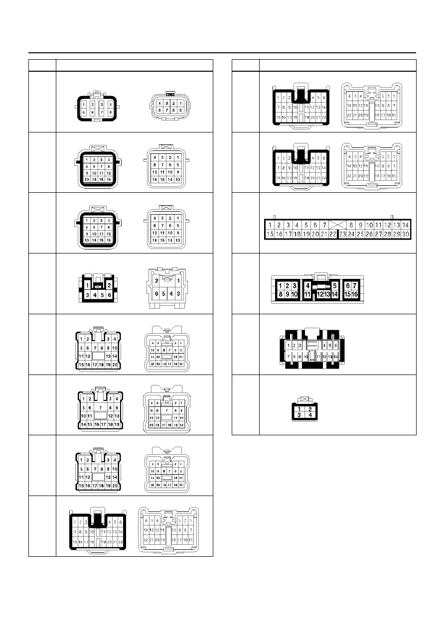


3F–14

INTELLIGENT SUSPENSION

F-7

H-5

H-6

H-11

H-12

H-14

H-15

H-16

No.

Connector face

H-18

H-25

I-1

I-2

I-9

I-18

No.

Connector face

INTELLIGENT SUSPENSION

3F–15

Diagnostic Trouble Code (DTC)
Identification

DTC No.

DTC NAME

CODE 

MEMORY

WARNING 

LAMP

2

Actuator Coil Over Current

Yes

OFF

3

Actuator Coil/Position Sensor Open Circuit or Short

Yes

ON

4

G-Sensor Open Circuit or Short

Yes

ON

5

Vehicle Speed Sensor Open Circuit or Short

Yes

OFF

6

Stop Lamp Switch Open Circuit, Short or Contact Point Trouble

Yes

OFF

7

Engine Speed Signal Open Circuit or Short

Yes

OFF

9

Control Unit Abnormality

Yes

OFF

3F–16

INTELLIGENT SUSPENSION

DTC2 Actuator Coil Over Current

Circuit Description

The A, B, C, and D are the actuator motor coil terminals.
DC 12V driving voltage is applied between terminals A
and C and terminals B and D so that the shock absorber
oil valves are rotated at every 7.5

° step feed.

Diagnostic Aids

• Inspect the wiring for poor electrical connections

between the control unit 24 way connector and the
actuator connectors. Look for possible bent, backed
out, deformed, or damaged terminals. Check for
weak terminal tension as well.
Also check for a chafed wire that could short to bare
metal or other wiring. Inspect for a broken wire inside
the insulation.

• When diagnosing for a possible intermittent short or

open condition, move the wiring harness while
observing test equipment for a change.

DTC2 Actuator Coil Over Current

Step

Action

Value(s)

Yes

No

1

1. Turn off the starter switch.

2. Disconnect the actuator connectors C–45, C–44,

F–7, and F–6.

3. Measure the resistance between the actuator side

connector C–44 terminals 1 and 2.

Is the resistance within the specified value?

6.4– 7.2

W

Go to Step 2   

Go to Step 3   

2

1. Measure the resistance between the actuator side

connector C–44 terminals 3 and 4.

Is the resistance within the specified value?

6.4– 7.2

W

Go to Step 4   

Go to Step 3   

3

Replace the actuator FR.

Go to Step 4   

4

1. Measure the resistance between the actuator side

connector C–45 terminals 1 and 2.

Is the resistance within the specified value?

6.4–7.2

W

Go to Step 5   

Go to Step 6   

5

1. Measure the resistance between the actuator side

connector C–45 terminals 3 and 4.

Is the resistance within the specified value?

6.4–7.2

W

Go to Step 7   

Go to Step 6   

6

Replace the actuator FL.

Go to Step 7   

7

1. Measure the resistance between the shock

absorber side connector F–6 terminals 3 and 4.

Is the resistance within the specified value?

6.4–7.2

W

Go to Step 8   

Go to Step 9   

8

1. Measure the resistance between the shock

absorber side connector F–6 terminals 7 and 8.

Is the resistance within the specified value?

6.4–7.2

W

Go to Step 10   

Go to Step 9   

9

Replace the rear shock absorber RR.

Go to Step 10   

10

1. Measure the resistance between the shock

absorber side connector F–7 terminals 3 and 4.

Is the resistance within the specified value?

6.4–7.2

W

Go to Step 11   

Go to Step 12   

11

1. Measure the resistance between the shock

absorber side connector F–7 terminals 7 and 8.

Is the resistance within the specified value?

6.4–7.2

W

Go to Step 13   

Go to Step 12   

INTELLIGENT SUSPENSION

3F–17

12

Replace the rear shock absorber RL.

Go to Step 16   

13

If all steps are correct, check the continuity between
the control unit connector C–50 terminal 1 and
connector terminal C50–4, C50–17, C50–5, C50–18,
C50–6, C50–19, C50–7, C50–20, C50–8, C50–21,
C50–9, C50–22, C50–10, C50–23, C50–11, and C50–
24.
Is there continuity?

Go to Step 15   

Go to Step 14   

14

Repair the circuit.

Go to Step 16   

15

Replace the control unit.

Go to Step 16   

16

1. Reconnect all components, ensure all

components are properly mounted.

2. Clear the DTC.

Was this step finished?

Go to “Basic 

Diagnosis 

Flow". Go 

to 

Step 16   

Step

Action

Value(s)

Yes

No


Content   ..  1119  1120  1121  1122   ..